Ever wondered how ammeters display those precise readings and why protection systems kick in to disconnect equipment in the event of fault? The answer lies in a crucial component of electrical engineering: Current Transformers (CTs). These devices play a pivotal role in ensuring the smooth operation and safety of electrical systems. Let’s take a closer look at CTs and uncover their meaning, types and functionalities.
Also Read: Electrical Transformers | A Deep Dive into its Mechanics
What is Current Transformer?
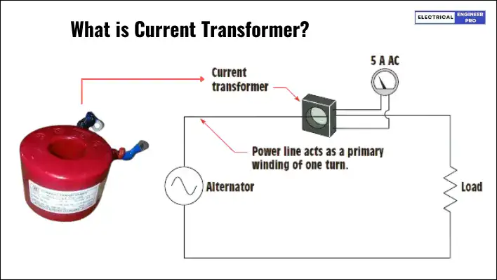
The basic function of Current Transformer is to sample line currents and scale them down to more safer, measurable levels. So that instruments such as ammeters, energy meters and watt-meters can accurately detect currents and provide precise readings.
The definition of the current transformer may not sound simple as its functions but offers a more detailed and precise description.
IEC 60044-1 that applies to newly manufactured current transformers from 15 Hz to 100 Hz says that current transformer is,
“an instrument transformer in which the secondary current, in normal conditions of use, is substantially proportional to the primary current and differs in phase from it by an angle which is approximately zero for an appropriate direction of the connections.”
Oddly the definition seems quite complex to understand, So, let’s simplify it.
Instrument Transformer: It means CT is a special kind of transformer made for measuring things in electronics. These transformers help lower high currents to levels that instruments can handle, like meters or protective relays.
Secondary Current Proportional to Primary Current: It conveys that the current in the secondary winding of the CT matches up with the current in the primary winding. So, if the primary current goes up or down, the secondary current goes down too, keeping everything in proportion. This configuration allows us to measure or monitor the primary current with great accuracy.
Phase Difference Approximately Zero: In an ideal situation, the current in the CT’s secondary winding lines up (in phase) perfectly with the primary current. This means they hit their peak values and zero crossings at the same time, making the phase difference close to zero degrees. When this happens, we get precise estimation of the primary current in the secondary circuit.
Appropriate Direction of Connections: This just means that the CT needs to be connected correctly to get accurate readings. CTs have polarity markings to ensure correct orientation during installation. Making sure it’s connected the right way ensures that the phase relationship between the primary and secondary currents stays spot on.
In summary, the definition outlines the characteristics of a current transformer where the secondary current is directly proportional to the primary current and maintains a phase angle difference close to zero degrees under normal operating conditions, provided it is connected correctly.
Also Read: Explore the Diverse World of DC Motors
Current Transformer Construction
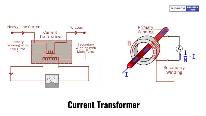
The design of a current transformer closely resembles that of a standard transformer, primarily functioning as a step-down device for current. It comprises primary and secondary windings, which are electrically isolated.
The correlation between these windings is determined by their respective number of turns and currents, known as the CT ratio, expressed as:
\frac{I1}{I2} = \frac{N2}{N1}
Where:
- N1 = Number of turns in the primary winding
- N2 = Number of turns in the secondary winding
- I2 = Current flowing through the secondary winding
- I1 = Current flowing through the primary winding
To reduce current to a minimal level, the secondary winding typically possesses more turns than the primary. Additionally, the secondary winding is wound with a conductor of smaller cross-section, while the primary section employs a conductor with a thicker cross-section.
Both windings, primary and secondary, encircle a magnetic core composed of silicon steel laminations. This material is chosen for its high permeability, allowing efficient magnetic flux transfer, and low hysteresis losses, ensuring accuracy.
As per Faraday’s law of induction, the current in the primary winding generates a magnetic field, part of which links with the secondary winding, inducing a current in it. The magnetic core facilitates a path of low reluctance for the produced magnetic field.
In smaller line voltage systems, current transformers typically use tape or varnish for insulation, whereas oil-immersed ones are preferred for higher line voltage systems due to their superior dielectric properties and effective heat dissipation.
In practical applications, the high-current line supplies power to the load. The primary side of the current transformer is connected in series to the high-current line, while the secondary side is linked to a low-range ammeter (0-5A) to measure the current flowing through it.
Also Read: AC Motor | Construction, Types, Advantages & Applications
Current Transformer How it Works?
Now that we understand the definition and construction of a Current Transformer (CT), and its vital role in producing manageable levels of currents that can be safely measured by instruments or protective relays, let’s explore the operational principles behind its function.
As we know, the primary section is connected in series with the circuit carrying the current to be measured, featuring thick windings with fewer turns. Whereas, the secondary consists of a greater number of turns of fine wire with a small cross-sectional area, connected to the measuring or protection device.
This primary-to-secondary winding configuration results in a step-down ratio, proportionally reducing the current from the primary to the secondary side.
For instance, consider a 1000:5 transformer used in conjunction with an ammeter. If the latter reads 7.5 A, the line current can be calculated as follows:
Primary (or line) current = 7.5 × (1000/5) = 1500 A
One of the best examples of a on how current transformer works is the clamp-on meter.
A clamp-on meter often incorporates a form of current transformer (CT) within its design. The clamp mechanism itself acts as the primary winding of the CT, enclosing the current-carrying conductor. When the clamp is closed around the conductor, it induces a voltage in the secondary winding of the CT, which is then measured and displayed as the current reading on the meter.
Also Read: In-Depth Guide to Variable Frequency Drives (VFD)
Types of CT Transformer
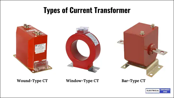
There are three basic types of indoor current transformers: Wound, Window and Bar.
Wound-Type Current Transformer
A wound current transformer is a type of transformer featuring separate primary and secondary windings encircling a laminated core. In its design, the primary winding is directly wound up on secondary winding with suitable insulation between two.
Physically, the primary winding is linked in series with the conductor through which the measured current flows in the circuit. The magnitude of the secondary current is determined by the turn’s ratio of the transformer.
Window-Type Current Transformers
In Window-type current transformers (CTs) the core of the transformer has a window-like opening. This opening allows for the primary conductor, typically a bus bar or cable carrying the current to be measured, to be passed through the CT without the need to disconnect it from the circuit.
The primary conductor passes through the window, and the CT surrounds it with its primary winding. This design makes installation and maintenance easier since the primary circuit does not need to be interrupted or disconnected for the CT to be installed or replaced.
Window type CTs are also called Toroidal CTs or Ring-type CTs because of a toroidal or ring-shaped core through which the primary conductor is passed.
Window-type CTs are commonly used in applications where it is impractical or unsafe to disconnect the primary conductor, such as in high-voltage power distribution systems or in situations where continuous operation is required.
Bar-Type Current Transformer
A bar-type current transformer (CT) is a specialized version of a window-type CT.
In a bar-type CT, a solid conducting bar, often made of copper or aluminum, is permanently placed through the window or opening in the CT core. This solid bar serves as the primary conductor of the CT.
The primary purpose of the bar-type CT is to measure the current flowing through the bar itself. The CT core surrounds the bar, and the secondary winding is wound around the core. When current flows through the bar, it induces a current in the secondary winding of the CT, which can then be measured to determine the current in the primary circuit.
Also Read: Decoding DOL Motor Starter | A Complete Guide
Classification of Current Transformer
CTs are typically classified based on their intended application as either Metering class or Protection class. Both types of CTs exhibit transformation errors, which are evaluated differently depending on operating conditions. In Metering class CTs, transformation errors are primarily considered under normal load conditions, whereas in Protection class CTs, they are assessed under abnormal (fault) conditions.
Metering Class CT
Metering class CT, also known as Instrument Class CT, is a type of current transformer primarily designed for accurate measurement of electrical parameters such as current, voltage, power, and energy. These CTs are specifically engineered to minimize transformation errors under normal operating conditions.
Metering class CTs are often employed in applications where precise monitoring and recording of electrical quantities are essential, such as billing, load analysis, and power quality assessment.
Metering class CTs are constructed to provide high accuracy over a wide range of currents, ensuring precise measurement of electrical parameters. They maintain a linear relationship between primary and secondary currents within their operating range, minimizing distortion in the measured signals.
These CTs are designed to operate well below their saturation point under normal load conditions, preventing inaccuracies due to core saturation. They typically have lower burdens compared to Protection class CTs, as they are primarily focused on accurate measurement rather than withstanding high fault currents.
Protection Class CT
Protection class CTs, also known as Protective CTs, are a type of current transformer specifically designed for use in protective relaying systems. These CTs are engineered to withstand high fault currents and provide accurate current measurements under abnormal operating conditions, such as short circuits or other fault conditions.
Unlike metering class CTs, which prioritize accuracy under normal load conditions, protection class CTs focus on maintaining accurate current transformation during fault conditions. This means that protection class CTs are designed to operate reliably even when subjected to high levels of current that may occur during a fault event.
Protection class CTs typically have higher burdens compared to metering class CTs, as they are expected to handle the higher currents associated with fault conditions. They are also characterized by their ability to accurately represent the primary current to protection relays, allowing these devices to make critical decisions, such as tripping circuit breakers to isolate faulty sections of the electrical system.
Typical protection classes include 5P, 10P, and PS
5P & 10P Classes
These CTs are typically employed in over-current protection schemes, allowing for larger errors compared to measuring class CTs. Their high saturation voltage is determined by a factor known as the Accuracy Limit Factor (ALF). This factor denotes the multiple of the rated primary current up to which the rated accuracy is maintained for a given burden connected to the secondary.
ALF can be defined as the ratio between the voltage at over-current and the voltage at rated current across the burden. Specifically, it represents the ratio between the rated accuracy limit primary current and the rated primary current.
In classification terms, 5P signifies a 1% current error at rated current and a 5% composite error at the fault limit current. Meanwhile, 10P indicates a 3% current error and a 10% composite error at the fault limit current.
PS Class CTs
PS Class CTs are crucial components in specialized protection schemes like biased differential protection, restricted ground fault, and distance protection. They play important roles in scenarios where accurately determining accuracy class and rated burden is difficult and where transforming full primary fault currents is necessary.
During the transient phase of a heavy short circuit, core saturation is likely to occur in many protection applications. Consequently, the performance of current transformers during faults becomes a critical aspect in establishing an effective relaying scheme.
In the design of any current transformer, the primary concern is determining the maximum secondary winding voltage achievable before core saturation, a parameter known as the Knee Point Voltage.
For Differential Protection, Restricted Earth Fault Protection, or other unit protection schemes, maintaining consistent CT characteristics is crucial. Discrepancies in CT characteristics may result in secondary leakage current or even trigger the activation of protection elements during through-fault conditions. Additionally, it is preferable for current transformers to exhibit greater accuracy compared to standards like 5P10 or 5P20.
Hence, when integrating CTs into such protection schemes, manufacturers adhere to specified characteristics to ensure optimal performance. Here, a CT for protection applications must be defined not just by its Accuracy Limit Factor (ALF) but also by its Knee Point Voltage.
PS Class CTs are characterized by their Knee Point Voltage, a defining feature ensuring that the CT remains unsaturated during fault conditions, thus maintaining its effectiveness in protecting the electrical system.
Also Read: Electrical Machines | Discover the Basics
What is Knee Point Voltage?
The knee point voltage of a current transformer (CT) is a critical parameter that indicates the onset of saturation in the CT core.
Saturation occurs when the core reaches a point where increasing the excitation current (which is proportional to the primary current) doesn’t result in a proportional increase in the magnetic flux.
This phenomenon is crucial to understand because beyond the knee point, the relationship between excitation current and induced voltage becomes nonlinear.
To determine the knee point voltage, you’d typically draw a saturation curve by applying incremental voltage to the CT secondary (with the primary open) and measuring the corresponding excitation current. The curve illustrates how the CT responds to increasing levels of voltage.
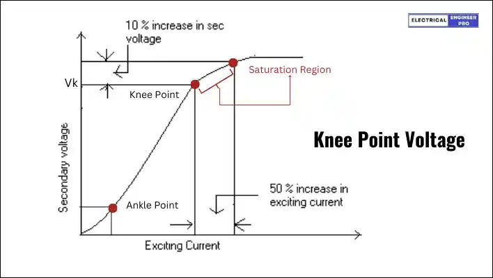
At the knee point, there’s a specific voltage (Vk) where a 10% increase in secondary voltage corresponds to a 50% increase in secondary current. This relationship demonstrates the onset of non-linearity in the CT’s response.
In practical terms, the knee point voltage is particularly important for Protection Class CTs used in protective relaying systems.
These CTs operate under high burdens, meaning they experience significant voltage drops across the connected loads.
If the voltage across the CT secondary exceeds the knee point voltage, the core may saturate, leading to inaccurate measurements and potentially compromising the protection scheme.
Therefore, ensuring that the knee point voltage is higher than the expected voltage drop across the burden is essential to keep the CT operating within its linear range and maintain accurate protection.
Burden of CT
The term “Burden” in the context of current transformers (CTs) refers to the total impedance or load that is connected to the CT’s secondary winding. This impedance is presented by the devices or equipment connected to the CT, such as protective relays, meters, or monitoring devices.
The term “Burden” is used because this impedance represents a load that the CT’s secondary winding must overcome to deliver accurate current measurements. Just like how a person carries a burden or load, the CT must work against this impedance to provide accurate output.
The burden on a CT is crucial because it directly affects the accuracy of current measurements and the performance of protective relays and metering instruments.
If the burden is too high, it can lead to voltage drop across the CT’s secondary winding, resulting in inaccuracies in current measurement. On the other hand, if the burden is too low, it can cause excessive current flow through the CT, potentially damaging it or posing safety hazards.
C.T. Secondary Open
It’s crucial to never leave the CT secondary open. Instead, it should either be shorted or connected in series with a low resistance coil, such as the current coils of a watt-meter or ammeter.
When the secondary is left open, the current through it drops to zero, resulting in zero ampere-turns being produced by the secondary winding. Since there’s no opposing magnetic field (counter mmf), the unopposed primary mmf generates excessive flux in the core, leading to increased core losses and overheating.
Additionally, heavy electromotive forces (emfs) are induced on both the primary and secondary sides, posing a risk of damaging the winding insulation. This also poses a danger to operators as well.
To mitigate these risks, it’s common practice to ground the CT on the secondary side to prevent electric shocks.
As a precaution, most CTs are equipped with a short circuit link or switch at the secondary terminals. Before energizing the primary winding, the short circuit link is closed to eliminate the risk of an open circuit on the secondary side.
Short-circuiting a current transformer poses no risk as the primary current remains constant and the secondary current cannot exceed what is determined by the turns ratio. The short-circuit across the winding can be safely removed once the secondary circuit is reconnected.
Uses of Current Transformer
Current transformers (CTs) have a wide range of applications in electrical systems due to their ability to accurately measure electrical currents and provide isolation and safety features. Some common applications of current transformers include:
- Metering: CTs are used in conjunction with watt-hour meters to measure the energy consumption of electrical loads in industrial, commercial, and residential settings. They give accurate readings of the current flow, enabling utility companies to bill customers based on their actual energy usage.
- Protection: CTs are essential components in protective relays and circuit breakers, where they monitor the current flowing through power lines and equipment. In the event of over-current conditions, such as short circuits or overloads, CTs provide signals to protective devices to trip the circuit and prevent damage to equipment and personnel.
- Monitoring and Control: CTs are used for monitoring and control purposes in electrical distribution systems. They offer instant data on current flow, enabling the engineers to monitor the health and performance of electrical equipment and adjust system parameters as needed.
- Power Quality Analysis: CTs are employed in power quality monitoring systems to analyze the quality of electrical power in terms of voltage, current, and frequency. By measuring current wave-forms, CTs help identify and diagnose issues such as harmonics and voltage sags which can affect the performance of sensitive equipment.
- Ground Fault Detection: CTs are utilized in ground fault detection systems to detect leakage currents in electrical circuits. By measuring the imbalance between phase currents and neutral currents, CTs help identify ground faults and trigger alarms or protective actions to isolate the faulted circuit.
- Transformer Protection: CTs are installed in power transformers to provide protection against over-current conditions and ensure the safe operation of the transformer. They monitor the current flowing through transformer windings and provide signals to protective relays to trip the transformer in case of abnormal conditions.
FAQs
How accurate are current transformers?
The accuracy of a current transformer depends on various factors such as its class, burden, and the quality of construction. Generally, CTs have high accuracy within their specified operating range, typically ranging from 0.1% to 10% of their rated current.
What is meant by the class of a current transformer?
The class of a current transformer indicates its accuracy under specified conditions. Common classes include Class 0.1, Class 0.2, Class 0.5, Class 1, and Class 5. The class designation corresponds to the maximum permissible error at rated primary current, with Class 0.1 being the most accurate and Class 5 having the widest tolerance.
What is CT current factor?
The CT (Current Transformer) current factor, also known as the “transformer ratio” or “turns ratio,” is the ratio of the primary current to the secondary current in a current transformer. It determines how much the primary current is reduced to a measurable level in the secondary winding.
What is CT accuracy?
CT accuracy refers to the degree of precision with which a current transformer (CT) measures and reproduces the primary current in its secondary winding under specified conditions.
Why is CT connected in series?
Current transformers (CTs) are connected in series within electrical circuits to measure the current flowing through a conductor. This setup enables the primary current passing through the conductor to also pass through the CT, producing a proportional secondary current. This secondary current is then available for measurement and various applications such as protection, monitoring, or control.
What is CT polarity?
CT polarity refers to the relationship between the current direction in its primary and secondary windings. In wiring, matching ends (P1 with S1, P2 with S2) denote the same polarity. In depolarization, current flows in the same direction from primary to secondary windings, while in additive polarity, it flows in opposite directions. Most commonly used CTs default to depolarization unless stated otherwise.
Why is a fuse not used in CT circuits?
A fuse is typically not used in CT (Current Transformer) circuits because CTs are primarily meant for current measurement, not over-current protection. On the secondary side of a CT, the current is directly proportional to the primary current without any source of over-current. Introducing a fuse in the secondary circuit, could lead to high secondary voltages that may damage insulation. Therefore, fuses are neither necessary nor desirable in CT secondary circuits.

