It is well known how Variable Frequency Drives (VFDs) usage has increased in motor applications. They’re employed everywhere, from air handlers and pumps to chillers and tower fans. Understanding these VFDs can actually make a big difference in how we choose and use equipment in electrical systems. This post is like a VFD 101, covering the basic terms, how they work, and its benefits.
Also Read: AC Motor | Construction, Types, Advantages & Applications
What Is Variable Frequency Drive (VFD)?
A Variable Frequency Drive (VFD) is a adjustable-speed drive integral to electro-mechanical drive systems, designed to regulate the speed and torque of AC motors by controlling and influencing the input frequency and voltage.
Widely applied in various contexts, from everyday electrical appliances like table fans and room air conditioning units to heavy industries relying on AC motors, VFDs have gained popularity despite encountering challenges such as heat generation, power losses, and the introduction of harmonics.
The fundamental technical principle at the core of VFDs is the precise control of motor speed. This control is achieved by aligning the motor speed with specific process requirements, thereby enhancing overall system efficiency.
The primary function of a Variable Frequency Drive can be summarized as follows:
- Step-less Speed Control: VFDs are employed for the step-less speed control of squirrel cage induction motors. These motors are widely used in process plants due to their ruggedness and maintenance-free long life.
- Sophisticated Speed Control Mechanism: VFDs control motor speed by adjusting output voltage and frequency through sophisticated microprocessor-controlled electronic devices. This level of precision allows for seamless and efficient speed adjustments tailored to the demands of the application.
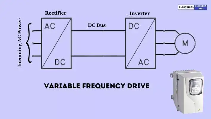
- Rectifier and Inverter Units: The structure of a VFD comprises rectifier and inverter units. The rectifier converts AC to DC voltage, and the inverter converts DC voltage back to AC voltage, enabling the necessary adjustments in voltage and frequency to achieve the desired motor speed.
In essence, a Variable Frequency Drive serves as a critical component in optimizing motor performance, offering precise speed control, and finding application across a spectrum of industries, demonstrating its significance in enhancing system efficiency.
Also Read: Explore the Diverse World of DC Motors
VFD Construction and Working Principle
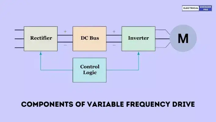
A Variable Frequency Drive (VFD) operates on four fundamental components: the rectifier, dc bus, inverter and control system. Understanding the operational principles of these sections is essential for grasping the functionality of a VFD.
Components of VFD
Rectifier
A full-wave, solid-state rectifier converts three-phase 50Hz or 60Hz power from a standard 415V or 220V higher utility supply to either fixed or adjustable DC voltage.
DC bus
After the rectification process, the power is stored on a DC bus. This DC bus is furnished with capacitors, serving the function of receiving, storing, and subsequently distributing power through the inverter section.
Inverter
The inverter transforms the filtered DC obtained from the DC bus into a pulsating DC waveform. Through precise control of the inverter’s output, the pulsating DC waveform can emulate an AC waveform at various frequencies.
Control System
An electronic circuit gathers feedback from the motor it drives and makes adjustments to the output voltage or frequency based on the chosen values. Typically, the output voltage is controlled to maintain a consistent voltage-to-frequency (V/Hz) ratio. The calculation process may involve numerous intricate control functions.
Working Principle of VFD
Rectifier
The basic function of a rectifier in a VFD is to convert incoming AC power into direct current (DC). Two rectifiers per phase are employed—one allowing power flow during positive voltage and the other during negative voltage.
For three-phase power supplies, a minimum of 6 rectifiers is used, resulting in a “6 pulse” drive. A VFD may incorporate multiple rectifier sections, making it “12 pulse,” “18 pulse,” or “24 pulse.”
Rectifiers utilize diodes, silicon-controlled rectifiers (SCR), or transistors.
Diodes are straightforward, allowing power flow when voltage polarity is correct. SCRs have a gate circuit enabling microprocessor control, useful for solid-state starters. Transistors, the most versatile, can open or close at any time.
Bipolar Transistor technology superseded over the old Silicon-Controlled Rectifiers (SCRs) in drives and Bipolar Transistors were surpassed by the adoption of Insulated Gate Bipolar Transistor (IGBT) technology.
DC bus
After the rectification process, the power is stored on a DC bus within the Variable Frequency Drive (VFD). This DC bus is furnished with capacitors, serving the function of receiving, storing, and subsequently distributing power through the inverter section.
Additional components, such as inductors, DC links, chokes, or their equivalents, are integrated into the DC bus to introduce inductance. This inclusion effectively smoothens the incoming power supply, contributing to the overall stability and reliability of the VFD operation.
Also Read: Synchronous Electric Generator | Principles & Working
Inverter
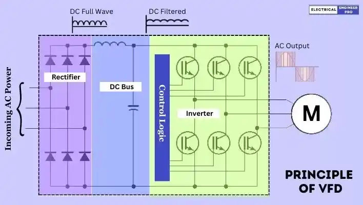
In the inverter section, an electronic control unit is linked to the transistor bases. This control unit performs the conversion of DC voltage back into three-phase alternating current by selectively turning transistors on or off at the appropriate time and in the correct sequence.
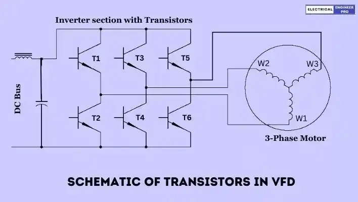
Consider, for instance, (refer above figure) the scenario where transistors T1 and T4 are simultaneously switched on. This configuration allows stator winding W1 to connect to a positive voltage, while W2 connects to a negative voltage. Current can then flow through T4 to W2, through the motor stator winding, and through W1 to T1.
Now, if transistors T1 and T4 are switched off, and transistors T3 and T6 are switched on, the current path shifts. Current will flow through T6 to stator winding W3, through the motor to W2, and through T3 to the positive side of the power supply.
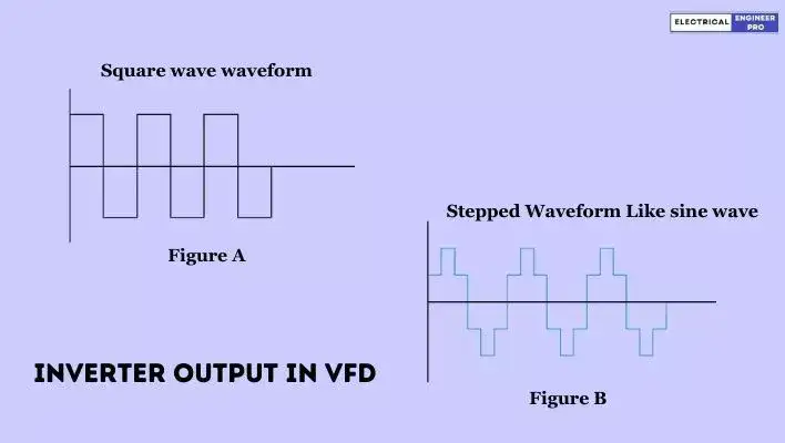
Due to the complete on-off control of transistors, the resulting waveform is a square wave rather than a sine wave (refer figure A). Induction motors can function reasonably well on a square wave. Some manufacturers design units to produce a stepped waveform (refer figure B) as it closely approximates a sine wave and addresses certain operational considerations.
In the inverter section there is an electronic control unit connected to the bases of transistors. Many transistor-controlled variable drives nowadays employ a special type of transistor called an insulated gate bipolar transistor (IGBT).
This control unit converts the DC voltage back into three-phase alternating current by turning transistors on or off at the proper time and in the proper sequence.
Control System
In Variable Frequency Drive (VFD), the control logic system plays a pivotal role in generating pulses essential for regulating the activation of power semiconductor devices, such as Silicon-Controlled Rectifiers (SCRs) and transistors.
The control circuitry, which involves intricate configurations, manages the switching of power devices. This coordination is commonly executed through a control board that prescribes the firing sequence of power components in a precise order.
In the inverter segment, an electronic control unit is linked to the transistors’ bases. Many modern variable drives that are transistor-controlled use a specific kind of transistor known as an insulated gate bipolar transistor (IGBT).
This control unit reverses the DC voltage into three-phase alternating current by strategically turning the transistors on or off in the correct sequence and timing.
Insulated Gate Bipolar Transistor (IGBT)
In many variable drives controlled by transistors, there’s a notable little component called an insulated gate bipolar transistor (IGBT). Now, the impressive thing about the IGBT is that it’s a voltage-controlled device, not a current-controlled one, thanks to its insulated gate with high impedance. This feature allows it to turn off lightning-fast.
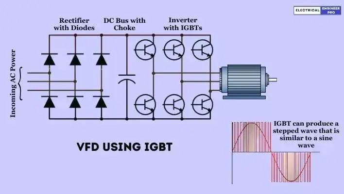
So, these drives with IGBTs, do not utilize the usual silicon-controlled rectifiers (SCRs) but only diodes to rectify AC voltage into DC.
In a three-phase rectifier supplying a steady DC voltage to the transistors. The output voltage to the motor is controlled by pulse width modulation (PWM).
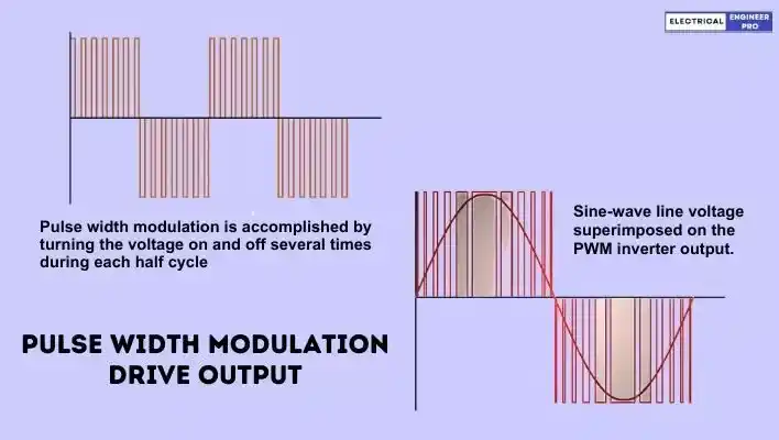
PWM controls the output voltage to the motor by flicking the transistors on and off multiple times during each half cycle. The resultant output voltage is an average of the peak voltage and depends on how long the transistor plays the on-off game.
For instance, let’s assume that 415 volts of three-phase AC is converted into DC, and after some filtering, we get around 600 volts for the IGBTs. Now, the output voltage to the motor is determined by the switching of the transistors.
If the transistor is ON for 10 microseconds and OFF for 20 microseconds, with it being ON for one-third and OFF for two-thirds of the time, the applied voltage to the motor would be 200 volts (600/3).
IGBTs operational speed is quick, thus creating a stepped wave that looks pretty close to a regular sine wave. So, in a nutshell, IGBTs and PWM team up to give us smooth motor control.
Also Read: Electrical Transformers | A Deep Dive into its Mechanics
Reason behind naming the drive as Variable Frequency Drive (VFD)
The synchronous speed of the motor, measured in RPM, is influenced by the frequency. Thus, by adjusting the frequency of the power supply using a Variable Frequency Drive (VFD), we can manage and control the speed of the synchronous motor.
Speed (rpm) = \frac{Frequency (hertz)\times 120}{No. of Poles}
Where;
Frequency = Electrical Frequency of the power supply in Hz.
No. of Poles = Number of electrical poles in the motor stator.
The above equation implies that the modification of motor speed variation is achieved by altering the frequency applied to the motor.
Alternatively, speed modification can be achieved by changing the number of poles, but this method involves a physical alteration of the motor.
The Variable Frequency Drive (VFD) accomplishes the necessary frequency and voltage output through Pulse Width Modulation (PWM) Drives, where a PWM inverter generates pulses of varying widths. These pulses are skillfully combined to construct the required waveform.
The VFDs capability to easily vary the frequency, in comparison to changing the motor’s poles, is the reason it is referred to as a Variable Frequency Drive.
Why do VFDs have to maintain constant V/f ratio at all speeds?
All Variable Frequency Drives (VFDs) have to maintain a constant output voltage-to-frequency (V/f) ratio across all speeds for specific reasons.
The relationship between phase voltage (V), frequency (f), and motor magnetic flux (ϕ) is expressed by the equation:
V = 4.444 f N ϕm
Or in terms of V/f:
V/f = 4.444 × N ϕm
Here, N represents the number of turns per phase, and ϕm denotes the magnetic flux.
If the same voltage is applied at a reduced frequency, the magnetic flux would increase, potentially saturating the magnetic core and distorting motor performance. To prevent this magnetic saturation, it is essential to maintain a constant magnetic flux (ϕm).
Additionally, the motor torque is the product of the stator flux and rotor current. To sustain the rated torque at all speeds, a constant flux must be upheld at its rated value. Achieving this involves maintaining a constant voltage-to-frequency (V/f) ratio.
This adjustment requires lowering the motor voltage proportionally with the frequency to prevent issues like magnetic saturation due to excessive flux or a decrease in torque below the rated value due to insufficient flux. Therefore, keeping the V/f ratio constant ensures stable and optimal motor performance across varying speeds.
Types of Variable Frequency Drive (VFD)
Pulse width Modulation (PWM)
The PWM drive has become widely adopted as a controller for motors in the range of approximately 1/2 horsepower to 500 horsepower. Most PWM units are rated at either 230 volts or 460 volts, three-phase, offering output frequencies spanning from about 2 Hz to 400 Hz.
In the PWM drive, the AC line supply voltage enters the input section and proceeds to a converter section. Here, a diode bridge converter and large DC capacitors generate and maintain a stable, fixed DC bus voltage.
The DC voltage then moves to the inverter section, typically equipped with insulated gate bipolar transistors (IGBTs), which regulate both voltage and frequency to the motor, producing an output resembling a near sine wave.
“Pulse width modulation” means each transition of the alternating voltage output comprises a series of short pulses with varying widths. By adjusting the pulse widths in each half cycle, the average power output mimics a sine wave. The frequency delivered to the motor is determined by the number of transitions from positive to negative per second.
IGBTs in a PWM drive can switch at speeds ranging from 2 kHz to 15 kHz. Modern PWM designs use power IGBTs operating at these higher frequencies. This results in a reduction of motor noise associated with Variable Frequency Drive (VFD) applications, as the motor windings oscillate at a frequency beyond human hearing. Additionally, the current wave shape to the motor is smoothed out by eliminating current spikes.
Voltage Source Inverter (VSI)
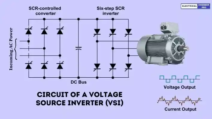
A Voltage Source Inverter (VSI), also known as a Variable-Voltage Inverter (VVI), employs a silicon controlled rectifier (SCR) converter bridge for the conversion of incoming AC voltage into DC. The SCRs serve as a means to control the rectified DC voltage.
Capacitors in the DC link between the converter and inverter store the energy. The inverter segment is equipped with six SCR switches. A microprocessor based control logic manages the switching of SCRs on and off, facilitating the provision of variable voltage and frequency to the motor.
This switching technique is commonly denoted as “six-step” due to its completion requiring six 60° steps for a full 360° cycle. Despite motors prefer a smooth sine wave, a six-step output is not smooth yet satisfactory for the motor to operate.
A notable drawback in this drive is torque pulsation, occurring each time an SCR is switched. This pulsation becomes evident at low speeds, resulting in speed variations in the motor, often termed as cogging. The non-sinusoidal current waveform induces additional heating in the motor, necessitating a motor de-rating.
In practical terms, Voltage Source Inverter drives have the capability to operate any number of motors up to the total rated horsepower of the drive.
Current source inverter (CSI)
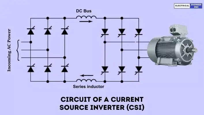
In a current source inverter, the DC power supply operates as a current source instead of a voltage source. These drives employ a closed-loop system to monitor the motor’s actual speed, comparing it with a preset reference speed. This process generates an error signal used to adjust the current to the motor—increasing or decreasing it accordingly.
The converter is linked to the inverter via a series inductor. This inductor opposes changes in current and possesses a sufficiently high inductance value to maintain almost constant direct current. Consequently, the output approximates a square wave of current.
Current-source inverters find application in large drives, typically around 200 horsepower. Their appeal lies in simplicity, regenerative braking capabilities, reliability, and lower cost. As current-source inverters monitor the actual motor speed, they are best suited for controlling a single motor with characteristics matching the drive.
Flux vector drive
A flux vector drive utilizes motor feedback to adjust its output, relying on the fundamental volts per hertz principle to control the motor. These combined techniques not only regulate the magnitude of motor flux but also its orientation, hence the name “flux vector.”
This method enhances motor speed and torque control precision. Unlike basic V/Hz control, flux vector control considers both magnitude and angle between voltage and current. V/Hz drive control, in contrast, focuses solely on magnitude.
Vector drives exist in two forms: open loop and closed loop, based on their feedback mechanism. Despite the term “open loop,” it functions as a closed-loop system, obtaining feedback internally from the Variable Frequency Drive (VFD) itself rather than an external encoder.
Due to this, there’s a tendency to refer to open-loop drives as sensor-less vector drives. Sensor-less vector control eliminates a significant source of complexity, streamlining the drive installation process.
Harmonics generated by Variable Frequency Drives (VFD)
In most variable frequency drives (VFDs), a bridge rectifier is used to convert incoming AC voltage into DC voltage, followed by an inverter which converts the DC voltage into a controlled voltage and frequency for speed control of the motor.
Currently in most VFDs, a diode bridge rectifier is used to transform the AC power line into a fixed-voltage DC bus with a capacitor bank for AC ripple filtration.
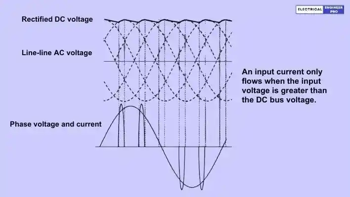
While this design enhances drive efficiency, it introduces challenges in the form of harmonics generation, particularly in the AC power line. Following are the reasons,
- The bridge rectifier converts AC voltage to DC voltage during a specific time period for each phase. Energy transfer to the DC bus occurs only when the input voltage is higher than the DC bus voltage, happening briefly in each phase (refer above figure).
- To transfer the required energy to the motor within this short time-frame, the peak current during these periods becomes high.
- The input current exhibits a non-sinusoidal waveform due to the rectification process. It comprises two discrete pulses per half-period, resulting in a high level of harmonic distortion.
- The current pulses are centered in the voltage period, yielding an almost one displacement power factor.
These non-sinusoidal current characteristics are common in modern electronic equipment utilizing bridge rectifiers, such as VFDs. Due to the non-proportional relationship between current and supplied voltage, these loads are termed non-linear loads. Non-linear loads contribute to harmonic distortion in the power system.
Various strategies exist for mitigating harmonics, and among them are several commonly employed methods:
- Line Reactor Installation: The use of a line reactor before a Variable Frequency Drive (VFD) introduces additional attenuation to the AC power supply, aiding in harmonics mitigation.
- DC Link Chokes: Employing DC link chokes, positioned in pairs on both the positive and negative buses of the VFD, contributes to harmonics reduction.
- 12 Pulse and 18 Pulse Drives: Opting for 12 pulse and 18 pulse drives, as opposed to 6 pulse drives, helps cancel some of the lower-level, higher-amplitude harmonic currents.
- Passive Filters: Utilizing passive filters that consist of a tuned configuration of capacitors, inductors, and, in some cases, resistors contributes to harmonics mitigation.
- Active Harmonics Filter: The use of an Active Harmonics Filter is another effective method for addressing harmonics, providing active compensation to counteract unwanted harmonic currents.
These approaches offer a range of options to address harmonics, allowing for tailored solutions based on specific system requirements and characteristics.
Variable Frequency Drive Applications
Variable Frequency Drives (VFDs) find applications in various industries and processes where precise control of motor speed is essential. Here are some common applications of VFDs:
- HVAC Systems: VFDs are extensively used in Heating, Ventilation, and Air Conditioning (HVAC) systems to control the speed of motors driving fans and pumps. This enables energy savings and precise control over airflow and temperature.
- Pumping Systems: VFDs are employed in water pumping systems to regulate pump speed based on demand. This is particularly useful in water supply networks, wastewater treatment plants, and irrigation systems.
- Industrial Fans and Blowers: In manufacturing facilities, VFDs are used to control the speed of industrial fans and blowers. This assists in maintaining optimal air circulation, cooling, and ventilation.
- Conveyor Systems: VFDs are applied in conveyor systems to control the speed of motors driving conveyor belts. This allows for efficient material handling and can be adjusted based on production requirements.
- Machine Tools: VFDs play a crucial role in machine tools, regulating the speed of motors in lathes, milling machines, and other machining equipment. This provides flexibility and precision in manufacturing processes.
- Extruders and Pumps in the Plastic Industry: In the plastic industry, VFDs are utilized in extruders and pumps to control the speed of motors, ensuring precise control over the extrusion process and fluid flow.
- Compressors: VFDs are applied in air compressors to adjust the speed of the motor based on the required air pressure. This helps in energy efficiency and reduces wear on the equipment.
- Centrifuges in Laboratories: VFDs are used in laboratory centrifuges to control the rotational speed of the centrifuge rotor. This is critical for separating particles in various research and testing applications.
- Crushers and Mills in Mining and Aggregate Industries: In mining and aggregate industries, VFDs regulate the speed of crushers and mills, providing flexibility in processing and optimizing energy consumption.
- Elevator Systems: Elevator systems often employ VFDs to control the speed of the motor, allowing for smooth acceleration, deceleration, and precise floor leveling.
These applications highlight the versatility of VFDs across different sectors, offering energy savings, improved process control, and extended equipment lifespan.
Also Read: Types of High Voltage Circuit Breakers | Explained
FAQs
What are the main components of variable frequency drive (VFD)?
The main components of VFD are Rectifier, DC bus, Inverter and Control Logic.
How does a VFD work?
A VFD works by converting the incoming AC power to DC and then inverting it back to a variable frequency and voltage AC power, allowing precise control over the motor speed.
What are the main benefits of using a VFD?
Using a VFD can result in energy savings, improved process control, reduced wear and tear on equipment, and enhanced overall efficiency in various industrial applications.
In what applications are VFDs commonly used?
VFDs are widely used in applications such as pumps, fans, conveyor systems, HVAC systems, and other machinery where variable speed control is essential for optimizing performance and energy consumption.
Can a VFD be retrofitted into existing systems?
Yes, VFDs are often designed to be retrofitted into existing systems, providing an economical way to upgrade older equipment and improve overall efficiency without the need for a complete replacement.
What kind of motors are compatible with VFDs?
VFDs are compatible with various types of motors, including induction motors and permanent magnet motors. It’s essential to check the motor specifications and ensure compatibility with the chosen VFD.
How can a VFD contribute to energy efficiency?
VFDs enable energy savings by allowing motors to operate at variable speeds based on the actual demand, preventing the need for constant full-speed operation and reducing unnecessary energy consumption.
How do VFDs contribute to motor protection?
VFDs offer motor protection features such as overload protection, voltage and current monitoring, and fault detection, which help prevent motor damage and extend the lifespan of the equipment.