The potential transformers are crucial in power systems, acquiring voltage signals for metering and system protection. Without potential transformers, measuring voltage would become a daunting task. So lets explore how it works, principles, diverse applications, and types, illuminating its pivotal role in electrical engineering.
Also Read: What is Current Transformer? How it Works?
What is a Potential Transformer?

Electricity travels through many substations on its way from power plants to your home. At each substation, voltage is adjusted either up or down, depending on its intended purpose.
Before electricity reaches your homes and businesses, it’s crucial to ensure that the voltage is just right and there is no voltage drop along the way. That’s why we need to measure voltages at different points.
However, for measuring voltages, you cannot directly connect voltmeters across the live distribution line. A voltmeter cannot operate on the high voltages found in substations. That’s where potential transformers come in.
They act like converters, turning high voltages into lower output voltages that voltmeters can handle, providing precise readings.
Also Read: Decoding DOL Motor Starter | A Complete Guide
Definition of a Potential Transformer
The definition of a Potential Transformer according to the IEC closely resembles that of a Current Transformer, with the only distinction being the exchange of the terms “current” to “voltage.”
IEC defines Potential transformer as an,
“Instrument transformer in which the secondary voltage, in normal conditions of use, is substantially proportional to the primary voltage and differs in phase from it by an angle which is approximately zero for an appropriate direction of the connections.”
Here’s a breakdown of the definition:
- Instrument Transformer: Potential transformers come under the category of instrument transformers that are commonly used to scale down high voltages or currents to levels that can be safely measured by instruments.
- Secondary Voltage Proportional to Primary Voltage: The voltage output on the secondary side is directly linked to the voltage input on the primary side. If the primary voltage changes, the secondary voltage changes proportionally.
- Phase Difference Close to Zero: The voltage on the secondary side closely follows the voltage on the primary side. This means they’re almost in sync or “in phase.” This signifies that the secondary voltage waveform aligns closely with the primary voltage waveform.
- Appropriate Direction of Connections: The phase relationship between primary and secondary voltages depends on how the transformer is connected in the circuit. When Potential Transformers are connected correctly, the phase angle between primary and secondary voltages is close to zero, meaning they are in-phase or nearly so.
In summary, this statement describes a voltage transformer (instrument transformer) that accurately scales down the primary voltage to a proportional secondary voltage with minimal phase difference, provided the transformer is connected correctly in the circuit.
Also Read: In-Depth Guide to Variable Frequency Drives (VFD)
Potential Transformer Uses
Potential transformers have a wide range of uses in electrical systems, including:
- Voltage Measurement: They scale down high voltages so that voltmeter displays accurate measurement which cannot work on high voltages.
- Protective Relaying: Potential transformers provide voltage signals to protective relays, helping prevent disturbances and faults in electrical systems by initiating protective actions.
- Control Systems: In control systems, potential transformers provide voltage signals for regulating and controlling the operation of various devices and equipment such as voltage regulators, power factor correction panels, static Var compensators, transformer load tap-changers etc.
- Impedance and Power Calculation: They help calculate impedance and power in electrical systems by providing accurate voltage measurements. These measurements assist engineers in evaluating system performance, diagnosing issues, and implementing optimization strategies to improve efficiency, reliability, and stability.
- Security Monitoring: Potential transformers help determine over-frequency, over-voltage, under-voltage, ensuring system stability and reliability.
- Harmonic Analysis: Potential transformers are utilized in harmonic analysis to assess the presence of harmonic distortions in voltage wave-forms, which can affect the performance of electrical equipment and systems.
- Isolation: Potential transformers ensure safety for personnel and equipment during voltage measurement and monitoring by providing electrical isolation between the high-voltage primary side and the low-voltage secondary side.
Also Read: Synchronous Electric Generator | Principles & Working
Construction of Potential Transformer

Like all the traditional power transformers, potential transformers are made up of primary and secondary windings. The voltage generated at the load side is directly proportional to the ratio of secondary turns to primary turns. This voltage transformation can be expressed by the equation:
V1V2=N1N2
Where:
- V1: Voltage applied to the primary winding of the transformer
- V2: Voltage produced at the secondary (load) of the transformer
- N1: Number of turns in the primary winding
- N2: Number of turns in the secondary winding
For instance, if a transformer has N1=10 and N2=100, with a primary winding voltage V1 of 100 volts, the secondary winding voltage will be 10 volt.
A potential transformer features a magnetic core composed of large silicon laminations. This core can be either shell-type or core-type configurations.
The secondary side of the winding is placed close to the core. On the other hand, the primary winding, which carries high voltage, is wound over the secondary winding with insulation in between.
Both windings are immersed in an oil-filled tank, providing superior insulation for high-rating voltage transformers. The high voltage terminals are extended outside the tank through oil-filled bushings to facilitate connectivity.
In Low voltage potential transformers, the windings are placed in epoxy or synthetic resin insulation.
Also Read: AC Motor | Construction, Types, Advantages & Applications
Working Principle of Potential Transformer
Potential transformers, like standard transformers, operate on Faraday’s law of electromagnetic induction. The primary winding has many turns, carrying the measured Voltage
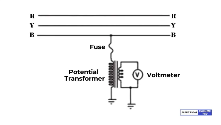
The high voltage line, whose voltage needs reduction, is connected in parallel to the primary windings. The secondary winding is then connected to a measuring device, such as a voltmeter or watt-meter, for voltage or power measurement.
As high AC voltage flows through the primary winding, it generates a magnetic field. This field induces a voltage in the secondary winding. With small number of turns, the secondary winding effectively reduces the voltage, enabling the connected device to accurately measure and display it.
The voltage ratio of a potential transformer is determined by the ratio of turns in the primary winding to turns in the secondary winding. For instance, if the ratio is 100:10, it reduces a primary voltage of 100 volts to a secondary voltage of 10 volts.
The accuracy of a potential transformer relies on factors such as the quality of the magnetic core, the number of turns in the windings, and the precision of the measuring instrument connected to the secondary winding.
Also Read: Explore the Diverse World of DC Motors
Potential Transformer Types
Electromagnetic Potential Transformer
An electromagnetic voltage transformer functions by converting a primary voltage into a secondary voltage through electromagnetic induction. Unlike other voltage transformers, it does not incorporate additional electrical components such as capacitors to alter the primary voltage.
Capacitive Potential Transformer

A capacitive potential transformer, also known as a capacitive voltage transformer (CVT), is an instrument transformer utilized in electrical power systems to precisely measure high voltage levels. It functions based on the principle of capacitance. Here’s an explanation of its operation,
Basic Principle: A CVT consists of a capacitor divider network and an electromagnetic unit. The capacitor network is connected in series with the line whose voltage is to be measured. The electromagnetic unit is connected across a low-voltage circuit and provides an output proportional to the voltage being measured.
Capacitor Divider Network: The capacitor divider network is made up of high voltage and low voltage capacitors. The high-voltage capacitor is linked in series with the power line. The voltage transformation ratio is determined by the ratio of capacitance in the two branches.
Electromagnetic Unit: The electromagnetic unit usually consists of a core with primary and secondary windings. The primary winding is fixed across the low voltage capacitor, and the secondary winding is connected to the measuring instrument or the load.
Voltage Measurement: When high voltage is applied to the series capacitor network, it produces a voltage across the capacitor in proportion to the high voltage. This voltage is then stepped down by the electromagnetic unit, providing a lower voltage output suitable for measurement by instruments or for control purposes.
In comparison to the electromagnetic voltage transformer, the capacitive voltage transformer offers numerous advantages in terms of both economy and safety. Additionally, it effectively prevents ferromagnetic resonance caused by core saturation in voltage transformers.
Optical potential Transformer
An optical potential transformer is a game-changer in voltage measurement. It uses optical materials instead of traditional iron cores, avoiding issues like magnetic saturation and accuracy loss. Instead of copper coils, it relies on optical fibers to transmit signals, ensuring precise readings.
OVTs operate on different optical principles, with the Pockels effect being the most common. However, this method requires many optical components and faces challenges in calibration and mass production.
Despite these hurdles, OVTs offer exceptional accuracy and immunity to electromagnetic interference. They come in handy across various frequencies, making them crucial in critical electrical measurement tasks.
Also Read: Electrical Transformers | A Deep Dive into its Mechanics
Potential transformer and Current transformer
Difference between Potential Transformer and Current Transformer.

| Potential Transformer (PT) | Current Transformer (CT) | |
| Function | Measures and reduces high voltage to a lower level for measurement. | Reduces high current to a manageable level for measurement. |
| Types | Electromagnetic Potential Transformer Capacitive Potential Transformer Optical potential Transformer | Wound Current Transformer Window-type current transformers Bar-type Current Transformer |
| Connection | Connected in parallel with the circuit where voltage is to be measured. | Connected in series with the circuit carrying the current to be measured |
| Primary Winding | More turns, carries the voltage to be measured. | Fewer turns, carries the current to be measured. |
| Secondary Winding | Fewer turns, connected to the meter or instrument. | More turns, connected to the current winding of the instrument. |
| Core | Designed with top-quality steel operating at low flux densities. | Designed with silicon steel lamination. |
| Primary Current | Depends on secondary side circuit conditions. | Independent of secondary side circuit conditions. |
| Secondary Side | Can be open-circuited without damage. | Cannot be open-circuited during service. |
| Burden | Depends on the secondary burden. | Does not rely on secondary burden. |
| Applications | Power source, measurement, protective relaying. | Measuring current and power, monitoring the power grid operation, protective relaying. |
FAQs
What if the secondary of a potential transformer is short-circuited?
If the secondary circuit is short-circuited, the impedance drops to near zero, causing a surge in current. This can damage secondary equipment and pose a safety risk to personnel.
How does a potential transformer work?
A potential transformer works on the principle of electromagnetic induction. It consists of primary and secondary windings, where the primary winding is connected in parallel to the high voltage circuit and the secondary winding is connected to the measuring or protection devices. The transformer steps down the voltage in proportion to the turns ratio between the primary and secondary windings.
What are the typical applications of potential transformers?
Potential transformers are commonly used for voltage measurement, protection, and control in various electrical systems, including power transmission and distribution networks, industrial plants, and commercial facilities.
How do potential transformers differ from current transformers?
While potential transformers step down voltage for measurement and protection purposes, current transformers (CTs) step down current. Both types of transformers are essential components of instrument transformers used in power systems, but they serve different functions based on the type of electrical parameter being measured or monitored.
Can potential transformers be installed indoors and outdoors?
Yes, potential transformers are designed to be installed in various environments, including indoor and outdoor locations. However, proper consideration should be given to factors such as environmental conditions, temperature extremes, moisture, and exposure to contaminants to ensure optimal performance and longevity.