Are you finding insulation resistance a bit confusing and wondering how it affects your electrical systems? Don’t worry, you’re not alone! Insulation resistance might sound a little technical, but this guide will break it down and make it easy for you to understand.
In this guide, we’ll walk you through why insulation resistance is important, how insulation resistance tests are done, what are the minimum values of insulation resistance and how factors like temperature, stress, humidity, etc can influence insulation materials over time.
So stick with us!
Star Delta Starter – How They Work & Why They Matter
What is insulation resistance
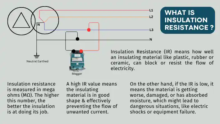
Insulation resistance is an important concept when it comes to electrical systems. It tells us how well an insulating material like plastic, rubber or ceramic, can block or resist the flow of electricity.
The job of insulation is to keep the electrical current where it’s supposed to be, flowing through the wires, without escaping to other wires or into the ground. If the insulation works well, it means the electrical system is safer and runs more efficiently.
Insulation resistance is measured in mega ohms (MΩ). The higher this number, the better the insulation is at doing its job.
A high insulation resistance value means the insulating material is in good shape and effectively preventing the flow of unwanted current.
On the other hand, if the insulation resistance is low, it could mean the material is getting worse, damaged, or has absorbed moisture, which might lead to dangerous situations, like electric shocks or equipment failure.
Testing insulation resistance is a common practice, especially in places like power plants, factories, and even homes, to ensure everything is safe and working as it should. Regular testing can help catch problems early before they become serious issues.
Potential Transformers – Principles, Types & Uses
Why Insulation Resistance fails
Insulation resistance is all about how well a material can block electrical current from passing through. For electrical systems, this resistance is crucial in keeping things safe and working smoothly. But over time, insulation can weaken or fail, and this happens for a few key reasons. Let’s look at these factors and how they impact insulation:
1. Electrical Stress
Insulation in electrical systems is typically designed for a specific job. But if the system experiences frequent over-voltages or under-voltages than the insulation can end up under abnormal stress.
This stress may cause tiny cracks or layers within the insulation to separate, weakening its ability to protect. Imagine stretching a rubber band too far; it eventually snaps. The same idea applies to insulation when it’s stretched by electrical stress.
2. Mechanical Stress
Mechanical stress refers to physical damage inflicted on insulation, often during construction, by unbalanced machinery, or by equipment that frequently starts and stops.
These actions generate vibrations that strain the insulation. Over time, this repeated movement can lead to tiny cracks or weaknesses, particularly in areas where the insulation endures constant jolts or vibrations.
3. Chemical Attack
Dirt, oil, and corrosive fumes can gradually degrade insulation, making it less effective. Think of it like dirt on your clothes—it’s not harmful right away, but over time, it wears the material down. Similarly, regular exposure to dirt, oil, or vapors can eat away at insulation, reducing its ability to protect.
4. Thermal Stress
Temperature changes also put pressure on insulation. Operating machinery in extreme heat or cold can make insulation expand or shrink, creating cracks and weaknesses.
However, even normal use of equipment creates thermal stress. Each time you start or stop a machine, the temperature changes, causing minor expansion and contraction in the insulation. Over time, these fluctuations add up and gradually age the insulation, especially if the machine isn’t built to handle frequent stops and starts.
5. Environmental Contamination
Environmental factors like moisture, humidity, and even pests can affect insulation. High humidity or moisture from nearby processes can lead to leaks or short circuits. Additionally, animals like rodents sometimes chew on insulation, which leaves the material compromised.
Simply put, exposure to various environmental factors over time can gradually wear down insulation’s resistance.
A Guide to Pump Efficiency Calculations for Energy Managers
Principles Insulation Resistance Test
Measuring insulation resistance is an essential part of ensuring electrical systems are safe and functioning properly. It helps determine if the insulating material around wires, cables, or electrical equipment is doing its job to prevent electricity from leaking.
This is done using a device called an insulation resistance tester, also known as a “mega-ohmmeter” or “Megger tester.” These devices apply a controlled voltage across the insulation and measure the resulting current flow to give an insulation resistance reading.
In simple terms, the tester sends a voltage through the material and checks how much current flows through it. If very little current flows, it means the insulation is strong and blocking the flow of electricity. If more current flows than expected, it could be a sign that the insulation is weakening or damaged.
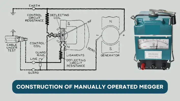
Working Principle of a Megger
A megger is a device used to measure insulation resistance, giving you an idea of how well the insulation in an electrical system prevents current from leaking out. To do this, the megger applies a voltage to the circuit and then measures the resistance. Let’s break down how it works step-by-step.
- Voltage Source – In traditional, hand-crank meggers, you generate the test voltage manually by turning a handle, which powers a small generator. This generator produces direct current (DC) that is used for testing. In modern digital meggers, a battery or a voltage converter supplies the required DC test voltage, making it simpler to use.
- Control Coil and Deflecting Coil – The megger has two main coils: the control coil (or pressure coil) and the deflecting coil (or current coil). The control coil is connected across the circuit and helps the megger measure voltage, while the deflecting coil is connected in series with the circuit, allowing it to sense the current flowing through.
- Current-Limiting Resistor – To protect the megger from damage, a current-limiting resistor is used. If there’s very low resistance in the circuit being tested (like a short circuit), this resistor prevents too much current from flowing through the coils and damaging the device.
- Pointer Deflection and Torque – The pointer on the megger’s dial moves in response to torque (rotational force) generated by the interaction between the control coil and the deflecting coil. Here’s how it works:
- When the insulation resistance in the circuit is high (meaning current can barely pass through), the torque from the voltage coil is strong, pushing the pointer towards the “infinity” side, indicating maximum insulation resistance.
- When the insulation resistance is low (meaning current can flow easily), the torque from the current coil dominates, pulling the pointer to the “zero” end of the scale, indicating minimal insulation resistance.
- If the insulation resistance is somewhere in between, the pointer settles at an intermediate point on the scale, showing a moderate level of resistance.
- How Resistance Levels Affect the Reading
- High Resistance = No Current Flow: If the insulation resistance is very high, the deflecting coil will have minimal or no current flow. This lack of current makes the pointer swing to “infinity,” showing strong insulation and no leakage paths.
- Low Resistance = High Current Flow: If there’s a short circuit or very low insulation resistance, the current will flow freely, and the deflecting coil will produce high torque. This pushes the pointer towards “zero,” indicating poor insulation.
- Intermediate Resistance = Varied Current Flow: For resistance values between zero and infinity, the pointer will settle between these two extremes. This reading helps users evaluate the quality of insulation—whether it’s adequate or may need maintenance.
- The Key Principle: The megger’s operation is based on Ohm’s Law (V = IR), where resistance (R) is calculated as voltage (V) divided by current (I). By adjusting the torque on the pointer, the megger visualizes the balance between voltage and current, providing a direct reading of insulation resistance.
Why Voltage Matters
Test voltage plays a big role in measuring insulation resistance. The higher the test voltage, the more likely it is to uncover small defects or weaknesses in the insulation.
For example, a 250-volt test may be sufficient for low-voltage systems, but larger or more critical equipment may require 1000 volts or more to reveal any hidden faults.
Components of Test Current
When we test insulation, we apply a test voltage and measure the resulting current. Using Ohm’s Law (R = V/I), we can determine the resistance of the insulation. However, it’s important to note that more than one type of current flows during this test, which can make things a bit tricky.
Let’s break down the four main components of test currents that you need to understand for an effective insulation resistance test.
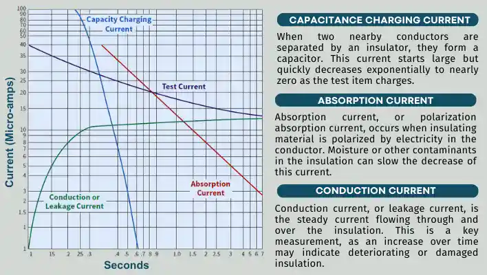
1. Capacitance Charging Current
Imagine two wires running close to each other, separated by an insulator, like a common two-wire electrical cord. These two wires when charged can act like a capacitor.
When we first apply the test voltage, the capacitive charging effect causes a current to flow until the voltage across the insulation matches the test voltage. Initially, this makes the resistance reading seem low, but it quickly rises as the insulation becomes fully charged.
Typically, this charging effect lasts less than a second, although it can extend to 30 minutes or more for longer cables or larger motors. While capacitance charging current itself doesn’t indicate insulation quality, it’s crucial to factor it in so that our measurements are accurate.
2. Absorption Current
Next up is absorption current, sometimes called polarization absorption current. This occurs as the insulating material becomes polarized due to the electricity flowing through it.
As the polarization level builds, the absorption current gradually decreases. This change reflects how the insulation stores potential energy.
Absorption Current has similar profile like capacitance charging current, but this time it happens at a much slower pace, lasting anywhere from a few seconds to over a minute.
Factors like moisture or contaminants can affect how quickly the absorption current decreases, making it an important indicator of the insulation’s integrity.
3. Conduction Current (Leakage Current)
Conduction current, often referred to as leakage current, is the steady current that flows through and over the insulation. An increase in leakage current over time usually signals that the insulation is deteriorating or damaged.
Initially, during the test, the measurements primarily reflect the capacitance charging current. After some time, the absorption current takes over. Typically, after about one to ten minutes, the readings are mostly influenced by conduction current. This value is crucial for calculating insulation resistance quality.
4. Surface Leakage Current
Lastly, we have surface leakage current. This type of current arises when the surface of the insulation is contaminated with moisture or salts. Unlike the other currents, surface leakage current remains constant over time and varies with the level of ionization, which can change with temperature.
While it’s often grouped with conduction current as part of the total leakage current, it’s good to be aware of it, especially in environments prone to contamination.
Step-by-Step Insulation testing Procedure
- Prepare the Equipment: Ensure the equipment is powered off, de-energized, and disconnected from any power source for safety and accuracy. Clean the insulation if it’s dirty or wet, as moisture or debris can impact the reading.
- Choose the Appropriate Voltage: Choose the appropriate test voltage for the equipment, usually between 250 to 1000 volts DC. Follow guidelines like IEEE Std 43 for specific recommendations.
- Connect the Tester: Connect the tester leads: one to the conductor and the other to the ground (usually the equipment casing or cable armor). Ensure secure connections to avoid inaccurate readings or hazards.
- Apply the Test Voltage: Turn on the tester to apply the selected voltage across the insulation. This allows the tester to measure the current flow, with higher voltages more likely to reveal weaknesses in the insulation.
- Monitor the Reading: Check the insulation resistance value on the tester’s display, usually in mega ohms (MΩ) or giga ohms (GΩ). Higher values indicate better insulation. Let the test run for about one minute, looking for steady readings, a dropping value may signal insulation issues.
- Interpret the Results: Compare the measured resistance to the recommended values for the equipment. Insulation resistance should be typically in the hundreds or thousands of mega ohms. Low values may indicate compromised insulation, requiring further inspection or replacement.
- Document the Findings: Document the test results, including resistance value, test voltage, duration, and any observations. Logging these measurements over time helps track insulation conditions and identify gradual deterioration.
Types of Insulation Resistance Test
Spot Reading Test
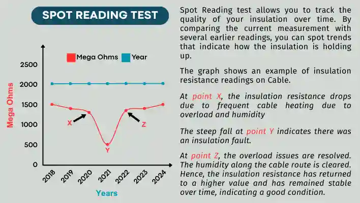
The Spot Reading test is one of the simplest ways to check insulation resistance. It involves applying a test voltage for a short period, typically 30 to 60 seconds and then noting the insulation resistance reading at that moment.
What’s really useful about the Spot Reading test is that it allows you to track the quality of your insulation over time. By comparing the current measurement with several earlier readings, you can spot trends that indicate how the insulation is holding up.
For instance, let’s say you conduct a Spot Reading test every six months. When you plot these results on a graph, you might notice a slow and gradual downward trend, which is normal as insulation ages.
However, if your latest measurement shows a sudden, significant drop in resistance, it could mean the insulation is deteriorating faster than usual. This change might indicate an underlying issue that needs your attention.
In such cases, it’s wise to schedule some downtime for the system to take a closer look. You might need to clean, upgrade, or even replace the insulation to prevent further problems.
By regularly performing the Spot Reading test, you can keep a close eye on your insulation resistance, ensuring that your equipment remains safe and efficient over time.
Polarization Index (PI)
The Polarization Index (PI) is a useful method for assessing the condition of insulation over time. To perform this test, you take two measurements of insulation resistance: one after 1 minute into the test and another after 10 minutes into the test. The PI is simply the ratio of the 10-minute reading to the 1-minute reading. In other words:
PI = (10-minute insulation resistance) / (1-minute insulation resistance)
Why does this matter?
The PI gives insight into how insulation behaves under a steady voltage over a longer period. A higher PI generally means better insulation quality. A PI value greater than 4 indicates excellent insulation, while a value below 2 can signal that the insulation is ageing or damaged, and further investigation might be needed.
| PI Value | Insulation Condition |
| < 2 | Problem |
| 2 to 4 | Good |
| > 4 | Excellent |
This test is particularly helpful for solid insulation systems like those in rotating machinery (motors and generators). According to IEEE standards, for rotating equipment with temperature classes B, F, and H, a PI of at least 2.0 is recommended.
In short, the Polarization Index is a powerful tool to help spot potential insulation problems early. It provides a quick snapshot of how the insulation stands up to stress over time, making it a popular test in maintaining electrical systems.
Dielectric Absorption Ratio (DAR)
In insulating materials, there’s a natural flow of current that fades away as the material absorbs it. This is called “absorption current.” For some types of insulation, this current decreases quickly, which can be a sign of healthy insulation.
The Dielectric Absorption Ratio (DAR) test checks how quickly this absorption current drops off over time by measuring the insulation resistance at two specific moments: after 30 seconds and after 60 seconds.
If the insulation is in good condition, the resistance reading after 60 seconds (R60) should be higher than after 30 seconds (R30).
The formula is simple:
DAR = R60 / R30
| DAR Value | Insulation Condition |
| < 1.25 | Problem |
| < 1.6 | OK |
| > 1.6 | Excellent |
A DAR ratio higher than 1 usually indicates that the insulation is absorbing current normally and is in good shape. On the other hand, a DAR below 1 may suggest that the insulation could be deteriorating or there might be moisture or contaminants affecting it.
So, for installations or equipment where the absorption current decreases quickly, like in many modern insulation materials, these 30-second and 60-second tests are often enough to give you a good picture of the insulation’s quality.
Nowadays, DAR test is less common with modern insulation systems but remains useful for older materials or when the Polarization Index (PI) is below 2, offering valuable insights into potential issues like ageing or moisture.
Step Up Voltage Test
A step voltage test involves testing insulation resistance at different voltage levels to assess the health of electrical insulation.
The test starts by applying a lower voltage and recording the resistance after a set interval, usually one minute. Then, the voltage is gradually increased in steps, and new measurements are taken after each step. Typically, this process is repeated over five voltage steps, but it may vary based on the equipment being tested.
The goal of this test is to stress the insulation, making it easier to spot potential weaknesses, like cracks or contamination, that might not show up at lower voltages.
If the insulation is dry, clean, and physically sound, you should see consistent resistance readings across the different voltages. However, if the resistance drops significantly as the voltage increases, it may be a sign of insulation breakdown, contamination, or moisture inside the insulation.
Minimum insulation resistance value acceptable
The minimum values of insulation resistance (IR) vary depending on the application, equipment, and voltage level, but here are some general guidelines based on international standards and best practices.
One Mega Ohm Rule
As per Indian Electricity Rules 1956, Chapter V – General Conditions Relating to Supply & Use of Energy, clause no. – 48(i)(b) under High Voltage Equipment Installations states that,
At a pressure of 1000 V applied between each live conductor and earth for a period of one minute the insulation resistance of HV installations shall be at least 1 Mega ohm or as specified by the [Bureau of Indian Standards] from time to time.
Which means,
1000V = 1KV = > 1 M ohms
11000 = 11Kv = > 11 M ohms
33000 = 33Kv = > 33 M ohms
Further under same clause – 48 (ii) states that,
Medium and Low Voltage Installations- At a pressure of 500 V applied between each live conductor and earth for a period of one minute, the insulation resistance of medium and low voltage installations shall be at least 1 Mega ohm or as specified by the [Bureau of Indian Standards] from time to time.]
The rationale behind these rule is not based on detailed engineering calculations but lies in practical experience. By setting a minimum insulation resistance, the rule help lower the chances of electrical breakdowns, ensuring that equipment stays in decent working shape.
Even though this rule might seem a bit odd, it is valuable in maintaining equipment safety and reducing risks related to moisture and contamination, which could otherwise degrade insulation and increase fault risks.
Minimum IR value for Motors
The IEEE-43 guide, Recommended Practices for Testing Insulation Resistance of Rotating Machinery, is all about how to measure and interpret insulation resistance in rotating machinery.
It covers the factors that can influence or change insulation resistance, suggests consistent testing methods, and provides formulas to calculate approximate minimum insulation resistance values for different types of AC and DC rotating machinery.
You can use the formulas in the table below to find the recommended minimum insulation resistance (Rm) for AC and DC machine armature windings, as well as for the field windings of both types of machines.
Minimum values at 40°C
| Minimum Insulation Resistance (Mega ohms) | Test Specimen |
| IR1min = kV + 1 | For most winding made before about 1970, all field windings and others not described below. |
| IR1min = 100 | For most AC windings built after about 1970. |
| IR1min = 5 | For most machines with random wound stator coils and form wound coils rated below 1kV and DC armatures. |
Minimum IR value for Transformer
A guide to transformer maintenance authored by S.D. Myers, J.J. Kelly & R.H. Parrish provides specific formulas for calculating the minimum insulation resistance in both dry-type and compound-filled transformers.
| [latex]R = \frac{CE}{\sqrt{KVA}}[/latex] |
| Where, |
| R = Insulation resistance of winding to ground to other winding grounded or between windings in mega ohms at 20°C. |
| C = 0.8 for oil filled transformers at 20°C. |
| C = 16 for dry, compound filled or untanked oil transformers. |
| E = Voltage rating of winding under test. |
| KVA = Rated capacity of winding under test. |
Minimum IR value for Cables
The Insulated Cable Engineers Association (ICEA) specifies minimum insulation resistance values for different types of cables and conductors. These values apply to new, single-conductor wires and cables that have passed an AC high-voltage test. The measurements are based on a DC test at 500 V, applied for 1 minute at 60°F.
For single-conductor cables, the standard minimum insulation resistance (IR) is calculated with this formula,
| IR = K log₁₀(D/d) |
| where: |
| IR = Insulation resistance measured in mega ohms per 1,000 feet of cable. |
| K = Constant specific to the insulating material. |
| D = Outside diameter of the conductor insulation. |
| d = Inside diameter of the conductor. |
Minimum values of K at 60°F/1000 feet
| Insulation Type | Constant |
| Impregnated Paper | 2640 |
| Varnished Cambric | 2460 |
| Composite Polyethylene | 30000 |
| Thermoplastic Polyethylene | 50000 |
| Polyvinyl Chloride at 60°C | 500 |
| Polyvinyl Chloride at 75°C | 2000 |
| Synthetic Rubber | 2000 |
| EP Insulation | 20000 |
| Cross-Linked Polyethylene (XLPE) | 20000 |
Understanding Insulation Resistance Test Results
Interpreting insulation resistance test results isn’t just about numbers; it’s about understanding the overall condition of your electrical systems and making informed decisions.
Let’s break down how to interpret these test results in a way that’s easy to understand.
1. Compare with Standards
First, always compare the measured insulation resistance values to the manufacturer’s guidelines or industry standards related to the specific equipment you’re testing. These benchmarks serve as a reference point, helping you understand whether the insulation levels are acceptable or if they raise any red flags.
2. Look for Trends Over Time
Next, it’s important to look at the insulation resistance values over time. Tracking these measurements can help you spot any trends or changes.
For example, if you notice a gradual decline in insulation resistance, this might signal that the insulating materials are wearing out. Identifying this early on allows for proactive maintenance or even timely replacements.
3. Check Consistency of Measurements
When taking insulation resistance measurements, consistency is key. Compare values from different points or terminals.
If you see significant differences between measurements, it could indicate localized issues or uneven degradation of the insulation. Addressing these inconsistencies early can prevent bigger problems down the road.
4. Consider Environmental Factors
Don’t forget to factor in the environment! Conditions like temperature and humidity can greatly affect insulation resistance readings. Always note these conditions during testing and adjust your interpretation accordingly. For instance, high humidity levels can lead to lower resistance readings, so understanding the context is crucial.
5. Identify Causes of Low Resistance
If you find low insulation resistance values, it’s important to dig deeper and identify potential causes. Common culprits include moisture, dirt, or physical damage to the insulation. By pinpointing the root cause, you can develop a targeted strategy to fix the problem and enhance safety.
6. Assess Risks and Make Decisions
Lastly, consider the risks associated with low insulation resistance. This could involve the risk of electrical leakage, short circuits, or other safety hazards. Use your test results to guide decision-making about maintenance, repairs, or replacements of affected components. A proactive approach can save time and resources while ensuring safety.
Power Formula with Power Factor | A Simple Explanation
Insulation Resistance FAQs
Can insulation resistance testing be done on live equipment?
No, insulation resistance testing should only be conducted on de-energized equipment to ensure safety and accuracy. Testing on live equipment can be hazardous.
Why is DC voltage applied in insulation resistance testing?
DC voltage is used because it provides a steady reading of insulation resistance without inducing capacitive or inductive effects that could interfere with accurate measurement.
What is a typical test duration for insulation resistance testing?
A test typically lasts between 1 to 10 minutes, with a 1-minute reading being common. Longer tests, such as 10 minutes, are used to calculate the polarization index, which helps assess insulation quality.
What’s the purpose of a guard terminal in a megger?
The guard terminal prevents surface leakage current from influencing the reading by providing an alternate path for leakage current, allowing the megger to measure true insulation resistance more accurately.
What are the limitations of insulation resistance testing?
Insulation resistance testing cannot locate the exact position of faults, nor can it measure internal insulation weaknesses effectively if these do not affect surface resistance. Additional tests may be needed for a complete assessment.

