Electrical transformers are equipment that are employed to transfer electrical power from one circuit to another through electromagnetic induction. These devices are widely used in power distribution, voltage regulation and isolation of different electrical systems.
This page highlights a comprehensive introduction to electrical transformers, including an explanation of what they are, how they work and why they are so important.
Whether you are an electrical engineer, a student or simply someone interested in learning more about electrical transformers, this write-up will provide a comprehensive overview of this fascinating and important machine.
Also Read: Decoding DOL Motor Starter | A Complete Guide
What is electrical transformer?
We all have studied the textbook definition of electrical transformers. Let’s check how international technical organizations define it, whose standards are followed by every major transformer manufacturer,
International Electrotechnical Commission standard IEC 60076-1 defines the transformer as:
A static piece of apparatus with two or more windings which by electromagnetic induction transform a system of alternating voltage and current into another system of voltage and current, usually of different values and at the same frequency for the purpose of transmitting electric power.
Whereas, The Institute of Electrical and Electronics Engineers standard IEEE C57.12.80-2010 and American National Standards Institute (ANSI) defines the transformer as:
A static electric device consisting of a winding, or two or more coupled windings, with or without a magnetic core, for introducing mutual coupling between electric circuits. Transformers are extensively used in electric power systems to transfer power by electromagnetic induction between circuits at the same frequency, usually with changed values of voltage and current.
From the definitions you understand that a transformer is an,
- Static apparatus with two or more windings.
- It utilizes electromagnetic induction.
- Transforms alternating voltage and current system into another system of voltage and current.
- Usually results in different values of voltage and current.
- Operates at the same frequency.
- Primary purpose is to transmit electric power.
- May or may not have a magnetic core.
- Introduces mutual coupling between electric circuits.
Now the definition does not provide answers with regards to its ratings, size, types, material composition, etc.
So it means that all the transformers possess somewhat the same properties and basic working principle whether they are core type, shell type, single phase, three phase, power transformer, distribution transformer, step-up, step-down, dry type, oil type, indoor, outdoor, on-load, off-load, etc.
Also Read: In-Depth Guide to Variable Frequency Drives (VFD)
What are the components of Electrical transformers?
The components of a electrical transformers depend upon its type.
For example, a dry type transformer, as its name suggests, doesn’t use oil for cooling or insulation. Instead, it relies on air or other suitable materials for these purposes.
Due to this difference, certain components found in oil type transformers may not be present in dry type transformers.
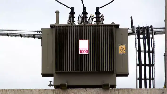
As oil type electrical transformers are more commonly used in transmission and distribution applications. These transformers have additional components that help them perform effectively in those specific situations.
So, let’s delve into the components typically found in oil type electrical transformers.
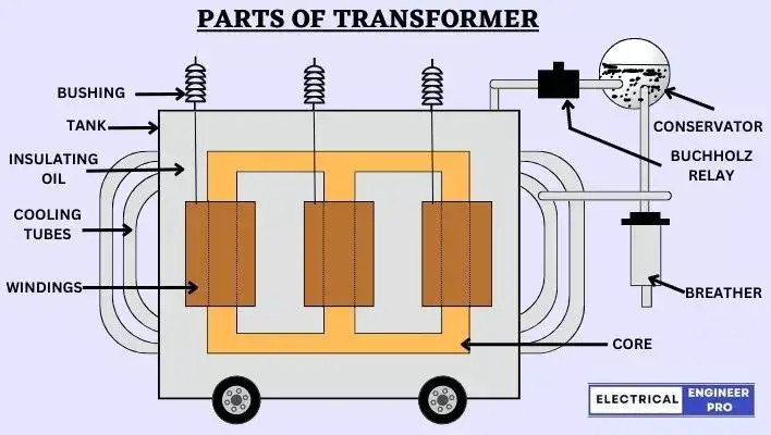
- Core: It provides a closed magnetic circuit for efficient energy transfer. Cores are usually made of laminated steel sheets to reduce eddy current losses.
- Windings: The transformer has two types of windings—primary winding and secondary winding. The primary winding is connected to the input power source, while the secondary winding is connected to the output load. The windings consist of insulated copper or aluminum wires.
- Insulation: Insulating materials such as paper, varnish, or oil are used to insulate the windings and prevent electrical breakdown between the turns and layers.
- Tap changer: This component allows for the adjustment of the transformer’s turns ratio, enabling voltage regulation to match varying load conditions. It provides multiple connection points along the winding for selecting different voltage levels. Tap changers are of two types – On Load Tap Changer (OLTC) and Off-Load Tap Changer.
- Tank: The tank encloses the core and windings and is typically made of steel. It provides mechanical support and protects the internal components from external environmental factors.
- Cooling system: Transformers generate heat during operation, so a cooling system is employed to maintain optimal operating temperature. Common cooling methods include oil-immersed cooling, where the transformer is immersed in insulating oil, or forced-air cooling, where fans circulate air over the windings.
- Bushings: These are insulated devices that provide connection points for the input and output conductors to the transformer. They ensure electrical insulation and secure connections. Low-voltage bushings are made of porcelain, ceramic or epoxy insulation while High-voltage bushing is a composite construction with a core of oil-impregnated or resin-bonded paper in an outer porcelain or epoxy cylinder.
- Conservator: It is a reservoir filled with insulating oil and connected to the main tank. The conservator compensates for oil volume changes due to temperature variations and provides additional insulation.
- Buchholz Relay: This protective device is installed in larger transformers. It detects and alerts for internal faults, such as insulation failure or the presence of gas, preventing further damage.
- Breather: The breather is a desiccant-filled container that prevents moisture from entering the transformer’s insulating oil as the oil expands and contracts with temperature changes.
principle and working of transformer
To get clarity on how the electrical transformers work, one must have a clear understanding of the phenomenon called Mutual Induction.
Let me break it down for you.
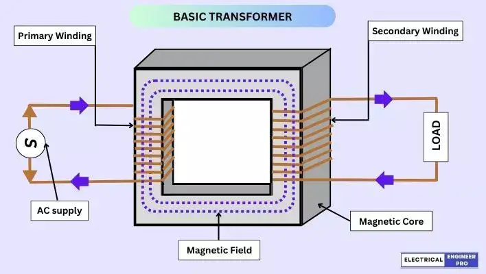
In a electrical transformers, the primary and secondary winding are on the same core.
When the primary winding is given an alternating (AC) supply, something magical happens and the core starts buzzing with a magnetic field or what we call a flux.
And guess what? The secondary winding, being right there on the same core, gets connected to this magnetic field.
As the magnetic field keeps changing and streaming around the core, it creates a kind of link with the secondary winding. This link induces a voltage in the secondary winding.
It’s like a secret power transfer going on between the windings. And this amazing ability of one winding to produce voltage in another is called Mutual Induction.
Wait, there’s more! The amount of voltage induced in the secondary winding is actually related to the number of turns in the windings.
Let me give you an example to make it clear.
Imagine the primary winding has 1000 turns of wire and is connected to a 250 V AC power supply.
When we do the math, we find that the transformer’s volts-per-turn ratio is 0.25.
How did we get that? We simply divided 250 V by 1000 turns, which gives us 0.25 V per turn (250 V/1000 turns = 0.25 V per turn).
Now, let’s focus on the secondary winding. Let’s say it has 500 turns of wire.
When mutual induction works its magic, the voltage induced in the secondary winding will be 125 V.
How do we get that? By multiplying the number of turns in the secondary winding (500) by the volt-per-turn ratio (0.25 V), we find that the induced voltage is 125 V (500 turns X 0.25 V = 125 V).
To sum it all up, electrical transformers operate based on the awesome principle of mutual induction.
It’s like these two separate coils, the primary and secondary windings, having a secret connection through their shared magnetic pathway.
It’s this connection that allows power to flow and voltage to be transformed.
Also Read: AC Motor | Construction, Types, Advantages & Applications
transformer and its types based on construction
So, when it comes to electrical transformers, there are different ways to classify them.
At its most basic level, electrical transformers can be divided into three main categories based on how the core and winding are arranged or configured.
(i) Core type, (ii) shell type and (iii) spiral core type.
Core Type
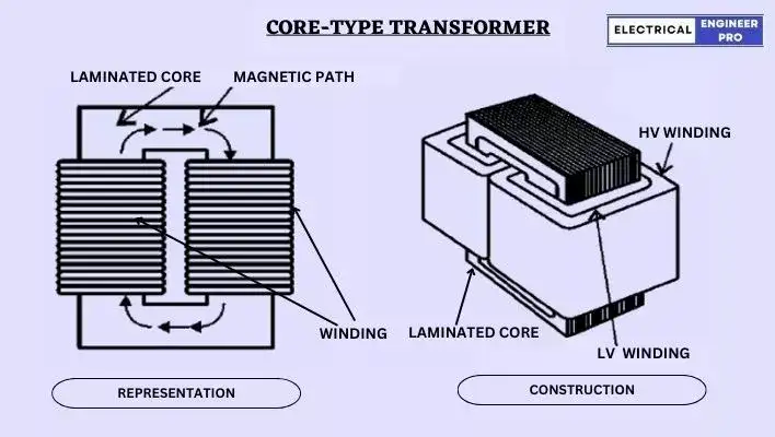
In core-type transformers, the windings wrap around a big chunk of the core. These coils are usually shaped like circles, ovals or rectangles.
Now, in an elementary core-type transformer, the core is made of rectangular laminated steel sheets. The primary winding is wound around the left leg of the core, while the secondary winding goes on the right leg.
This arrangement helps to keep the primary windings magnetic flux away from the secondary winding. As linking of magnetic flux causes energy losses called leakage flux.
In modern commercial core-type transformers, they use a different technique for the windings. They split the windings in half and put them on each leg of the core.
First, they wind the low-voltage one around the core, and then they place the high-voltage winding on top of it. This setup further reduces the leakage flux.
By splitting and layering the windings like this, the magnetic flux from the primary winding stays within its own section of the core.
This means it won’t mess around too much with the secondary winding. As a result, we get better efficiency and less energy loss in the transformer.
To sum it up, an elementary core-type transformer has a rectangular core made of laminated steel. The primary winding is on one leg, and the secondary winding is on the other.
In modern core-type transformers, they split the windings and position them on each leg, with the low-voltage winding first and the high-voltage winding on top. And that’s how they tackle the leakage flux issue.
Shell type
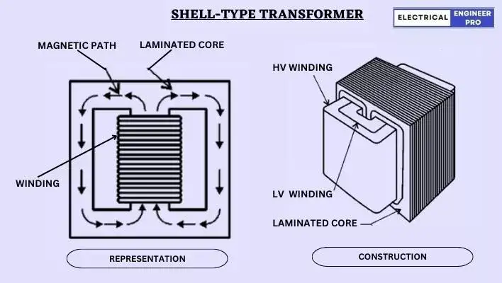
In a shell-type of transformer, both the primary and secondary windings are wrapped around the central “leg” of the core. It’s like windings are tightly hugging the central leg of the core.
In big commercial shell-type transformers, the windings actually pass through the inside of the steel core. It’s like the core forms a shell-like structure around the windings.
One neat thing about shell-type transformers is that they position the low-voltage coils closer to the iron core. This is done to minimize the need for high voltage insulation.
Here’s the deal though. Shell-type transformers have a larger core area, but they have fewer winding turns compared to core-type transformers with the same output and performance.
But there’s a downside to shell-type transformers. Since the windings are enclosed within the core, they don’t get much natural airflow for cooling. This can make cooling less efficient.
Also, if you ever need to do some maintenance and remove one of the windings, you’ll have to take apart a bunch of laminations. That can be a real pain, and it takes time and a lot of manual work.
So, that’s the scoop on shell-type transformers. They have a larger core area but fewer winding turns, cooling can be a challenge and as the windings hug the central leg of the core, removing the winding during maintenance can be a laborious job.
Spiral core
The spiral-core transformer utilizes the most recent advancements in core construction and is also referred to as the wound-core type or Spirakore transformer.
The spiral-core transformer employs the latest development in core construction by utilizing a continuous strip or ribbon of transformer steel wound in a circular or elliptical cylinder shape.
This unique construction allows the core flux to align with the grain of the iron. By using cold-rolled steel with a high silicon content, the designer can operate at significantly higher flux densities while reducing the loss per kilogram.
The higher flux density leads to a reduction in weight per kilovolt-ampere (kVA).
Therefore, the benefits of this construction approach include a stronger core, decreased weight and size compared to the kVA rating, reduced iron losses at higher operating flux densities and lower manufacturing expenses.
Also Read: Explore the Diverse World of DC Motors
Why is Electrical transformer efficiency so high? What are the losses?
Electrical transformers don’t have any moving parts to transmit energy. That means they don’t have to deal with friction or windage losses like rotating machines do.
And that’s one of the main reasons why transformers are so efficient.
But hold on, there are still some losses that occur in transformers. They are,
- Copper losses
- Core losses.
Copper Losses
Copper losses happen when current flows through the windings of the transformer.
They’re also known as load losses because they’re directly proportional to the amount of load being drawn from the transformer.
Basically, the more load you have, the more copper losses you’ll experience. You can calculate these losses by determining the resistance of each winding.
Now, even if there’s no load connected to the transformer, there’s still some energy loss due to the resistance of the primary winding to the magnetizing current.
This resistance generates heat in the winding, which needs to be cooled down by a cooling system.
Core Losses
Next, let’s talk about core losses. In a transformer, the magnetic material experiences something called hysteresis, which basically means losing energy because of heating.
This loss of energy shows up as heat not only because of hysteresis but also due to eddy currents in the magnetic path.
High temperatures caused by heat can greatly shorten the lifespan of the insulating materials used in the windings and structures.
However, if the cores are made of low-loss silicon steel and laminated properly, both eddy-current and hysteresis losses can be reduced.
It’s important to keep the transformer’s temperature in check because every 8-degree Celsius increase in temperature cuts the lifespan of the transformer in half.
So, maintaining a proper cooling system is crucial to ensure the transformer operates efficiently and lasts longer.
Why are Electrical transformers important?
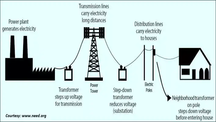
Let’s consider a scenario where you live in a rural area far away from the city. The nearest power grid is located several miles away. Now, in order to bring electricity to your home, a long-distance power transmission is required.
However, transmitting electricity over long distances at low voltages would result in significant energy losses due to the resistance in the transmission lines.
To overcome this, the electricity generated at the power plant is stepped up to a high voltage using a step-up electrical transformers.
So, the high-voltage electricity, let’s say 100 KV is sent through transmission lines to reach your area. Despite the long distance, the high voltage helps to minimize energy losses during transmission.
Once the high-voltage electricity reaches a local substation near your area, another transformer, known as a step-down transformer, is employed. This transformer reduces the voltage from, let’s say, 100 KV to the standard residential voltage of 415 V or 230 V.
Now, the lower voltage electricity can be distributed through local power lines to individual households, including yours.
By using transformers to step up and step down voltages, electricity can be efficiently transmitted over long distances and delivered to remote areas like yours.
Electrical transformers enable the expansion of the electrical grid, bringing power to communities that would otherwise be isolated or inaccessible.
In summary, electrical transformers are vital in long-distance power transmission scenarios. They help to minimize energy losses, ensure reliable electricity supply and extend access to electricity in remote areas.
Also Read: Synchronous Electric Generator | Principles & Working
Conclusion
In conclusion, electrical transformers play a vital role in the transmission and distribution of electrical power. They are essential devices that transfer electricity between circuits through electromagnetic induction. By utilizing the principle of mutual induction, transformers convert electrical energy from one system of voltage and current to another, allowing efficient power transmission.
Electrical transformers are important in power distribution systems as they enable the efficient transfer of electricity over long distances, minimizing energy losses that would occur due to resistance in transmission lines.
Whether in large power grids or small-scale applications, electrical transformers are indispensable components of electrical infrastructure. They allow for the expansion of electrical grids, bringing electricity to remote and inaccessible areas.
Overall, electrical transformers are fundamental devices that facilitate the efficient and reliable transmission, distribution, and utilization of electrical power, making them a cornerstone of modern electrical systems.