Welcome to our in-depth exploration of Direct Online (DOL) starters in this blog post. Discover the definition, understand the crucial parts, explore the principal functions, and weigh the pros and cons. Whether you’re a seasoned professional or just starting out, this guide is tailored to equip you with the knowledge needed to navigate the world of DOL starters effectively.
Also Read: AC Motor | Construction, Types, Advantages & Applications
What is DOL motor starter?
IS/IEC 60947-4-1 (2000) defines DOL as a “starter which connects the line voltage across the motor terminals in one step.”
It also states that “Direct-on-line starters intended to start and accelerate a motor to normal speed, to provide means for the protection of the motor and its associated circuits against operating overloads, and to switch off the supply from the motor.”
Based on the IEC definition and outlined statement of a DOL starter, we can conclude that,
- The DOL starter immediately applies the full line voltage to the motor without any gradual voltage buildup or reduction during the starting process.
- The main purpose of a DOL starter is to initiate and accelerate the motor to its regular operating speed.
- DOL starters are designed to provide protection for the motor and its associated circuits against operating overloads. This protection is crucial for preventing damage to the motor and ensuring safe operation.
- DOL starters also serve the function of switching off the electrical supply from the motor. This is essential for stopping the motor when needed, either during normal operation or in the case of an emergency.
In summary, according to IS/IEC 60947-4-1 (2000), a DOL starter is characterized by its immediate application of line voltage to the motor terminals in a single step.
Its primary functions include starting and accelerating the motor, protecting the motor and associated circuits from overloads, and providing a means to switch off the power supply to the motor. These features make DOL starters suitable for a range of applications where a direct and simple starting method is acceptable.
Good To Know
DOL (Direct-On-Line) starters are not used for large rating motors due to their drawbacks:
High Inrush Current: Large motors draw excessive current, causing voltage dips and disturbances.
Mechanical Stress: Immediate full voltage can stress motor components and reduce lifespan.
Impact on Power System: High inrush current affects power system stability.
Efficiency Concerns: Fixed-speed operation doesn’t suit large motors with variable loads.
Energy Efficiency Regulations: DOL starters may not comply with energy efficiency standards.
Overheating Risk: High starting current poses a risk of motor winding overheating.
For large motors, soft starters or variable frequency drives (VFDs) are preferred for controlled starting, energy efficiency, and reduced mechanical stress.
Parts of DOL motor starter
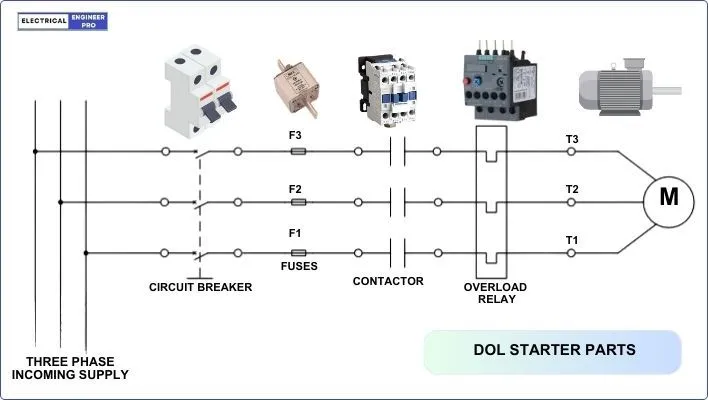
A Direct Online (DOL) starter typically consists of the following main parts:
Contactor
A contactor is an electrically operated mechanical device. In a motor control system, a contactor oversees the electrical flow to the motor. It comprises a coil that undergoes energization or de-energization to facilitate the opening or closing of the main contacts. For single-phase motors, 230V coils are used, while 415V coils are utilized in three-phase setups.
The contactor features line and load terminals along with auxiliary contacts. The line terminal connects to the incoming power supply, whereas the load terminal links to the load device, such as the motor.
Auxiliary contacts play a role in managing supplementary circuits like the start-stop, overload relay and timer.
Further, they contribute to energizing and de-energizing the magnetic coil upon pressing the start button. In the event of a detected current overload, the contactor swiftly breaks the circuit, stopping the motor as a preventive measure.
Also Read: In-Depth Guide to Variable Frequency Drives (VFD)
Overload Relay
When the motor draws high currents to fulfill the load demand, the current increases and goes beyond the permissible limit, such a situation is called Overload.
Electric overloads occur when an excess of current flows through electric wires or motor windings, posing risks of heat generation, equipment damage, and fire. To prevent this, Overload Relays are used as protection against overload.
An Overload Relay is a thermal device which senses the current flow in a motor and triggers a trip mechanism when it surpasses a preset limit. These relays are engineered to withstand the high inrush current during motor startup, featuring adjustable trip settings to trigger only when designated excess current flow is detected.
Good To Know: It's crucial to note that the overload relay does not offer short circuit protection. This role is fulfilled by over-current protective devices such as fuses and circuit breakers, typically found in the disconnecting switch enclosure.
There are three types of overload relays,
Electronic Relay – An electronic overload relay is a modern and advanced form of overload protection device used in electrical systems, particularly in motor control applications. Unlike traditional thermal overload relays, which rely on bimetallic elements to sense temperature, electronic overload relays use electronic components and sensors for more precise and adjustable current monitoring.
Thermal Relay – A thermal overload relay is a protective device used to safeguard electric motors from overheating due to excessive current. It operates based on the principle of heat-sensitive elements, typically bimetallic strips or heaters, which respond to the temperature rise caused by prolonged over-current conditions.
Magnetic Relay – Thermal overload relays operate on the heating and magnetic effect of current. The relay contains an electromagnetic coil that is connected in series with the motor’s power supply. When current flows through the coil, it generates a magnetic field. When the magnetic field generated by the coil goes beyond the set threshold, it sends a signal to the contactor to trip the motor.
Circuit Breaker or Fuse
The circuit breaker or fuse is incorporated in the DOL starter to protect the motor and the electrical circuit from ground faults, short circuits and over-currents due to overloading. It interrupts the electrical flow in case of a fault, preventing damage to the motor.
Push buttons
In a DOL starter circuit, two push buttons are present—a green start button and a red stop button. The start button, typically in the open position, initiates the motor by closing the circuit and applying power through the contactor when pressed.
On the other hand, the stop button, usually in the closed position, de-energizes the contactor coil and opens the contacts when pressed, disconnecting the motor from the power supply and halting its rotation.
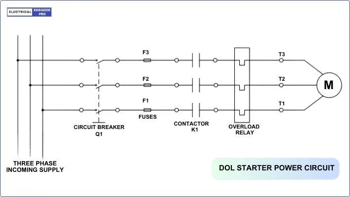
DOL Starter Power Diagram
A DOL (Direct-On-Line) starter power diagram refers to a schematic representation that illustrates the electrical connections and components involved in the power circuit of a DOL starter. This diagram provides a visual guide to understanding how the main components, such as the contactor, overload relay, and motor, are connected within the starter.
Also Read: Synchronous Electric Generator | Principles & Working
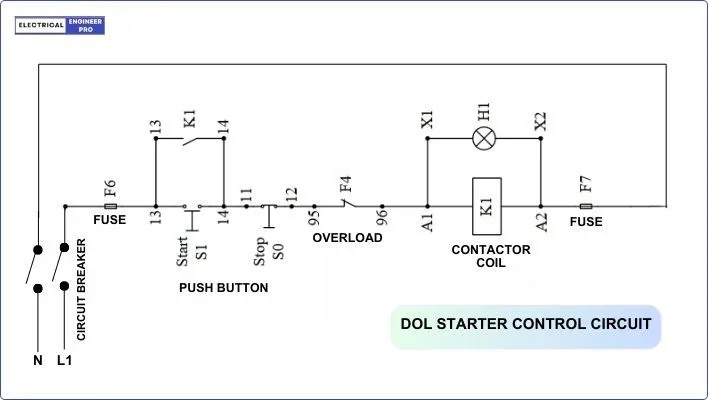
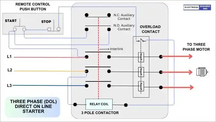
Control Diagram of DOL Starter
A DOL (Direct-On-Line) starter control diagram is a schematic representation that illustrates the control circuit of a DOL starter. This diagram provides a visual guide to the electrical connections and components involved in the control circuit, highlighting how various elements interact to start, stop, and protect the motor.
Wiring Diagram of DOL Starter
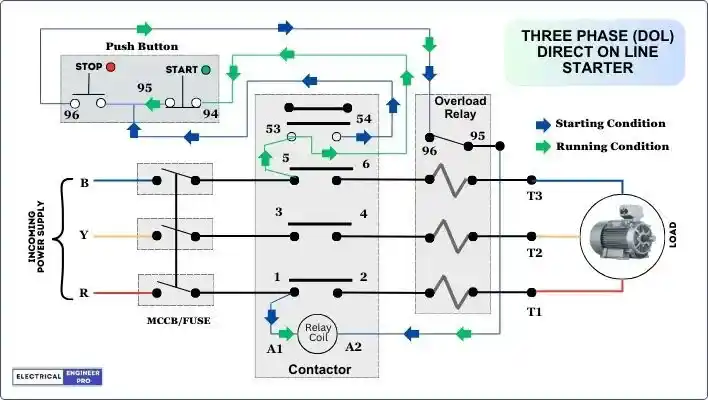
In the wiring diagram of a three-phase DOL starter, the incoming supply voltage from the main MCCB or fuse is directed to the Contactor. Through the contactor, the supply voltage is then channeled to the Relay Coil and Thermal Overload Relay. The wiring for the three phases is distributed as follows:
- The R Phase from the MCCB is connected to terminal 1 of the Contactor (NO).
- The Y Phase from the MCCB is linked to terminal 3 of the Contactor (NO).
- The B Phase from the MCCB is routed to terminal 5 of the Contactor (NO).
NO Contact:
- Terminal 53-54 represents a Normally Open (NO) contact in the contactor, closing when the relay energizes.
- Terminal 53 is interconnected with the Start Button terminal (94), while terminal 54 is associated with a common wire between the Start and Stop Buttons.
NC Contact:
- The Stop button (95-96) features a normally closed (NC) contact that opens when the thermal overload relay trips.
Relay Coil Connection:
- A1 of the Relay Coil connects to one of the Supply Phases.
- A2 is connected to the NC Connection (95) of the Thermal Overload Relay.
Thermal Overload Relay Connection:
- Motor terminals (T1, T2, T3) are connected to the Thermal Overload Relay.
- The Main Contactor and Motor are linked through the Overload Relay.
- The NC Connection of the Thermal Overload Relay is associated with the Stop Button, and the Common Connection of the Start/Stop Button.
This configuration ensures coordinated operation, allowing the contactor, relay coil, and thermal overload relay to facilitate start and stop functions while providing crucial protection against overloads.
Working of DOL Starter
Circuit Overview
- In the operation of a DOL starter, there are two distinct circuits: the power circuit and the control circuit.
- The power circuit delivers the necessary current to the motor, while the control circuit governs the switching of the power circuit.
- The control circuit features a push button board with start (Green) and stop (Red) buttons.
- The start (Green) button control circuit is connected to the B phase through terminal 5 and NO terminal 53 of the main contactor.
- The stop button is equipped with NC contacts and is connected to the relay coil A2 terminal through overload relay NC contact terminal 96-95.
Start Button Operation
- Pressing the start button transitions it’s NO contacts to NC, supplying voltage to the relay coil and energizing it.
- This energized coil signals the contactor to close its contacts, providing power to the motor.
- The control circuit remains active even after releasing the start button, ensuring a continuous power supply to the relay coil through NC contact terminal 96-95.
Stop Button Operation
- The current path through the contactor is broken when the stop (Red) button is pushed.
- The NC contact of the stop button becomes NO and the power supply to the relay coil is broken which de-energizes the coil.
- This de-energized coil prompts the contactor to open its contacts, effectively stopping power to the motor.
Thermal Overload Relay Action
- The thermal overload relay gets into action when the motor draws excessive currents, causing overheating.
- Operating on the electro-thermal characteristics of a bimetallic strip, the relay’s trip function activates when the strip heats up.
- This transition turns the NC contact 96-95 into a NO contact, interrupting power to the relay coil which opens the contactor contacts.
- The opening of contactor contacts caused by tripping of the overload relay, safeguards the motor from excessive heating.
- The trip function of the overload relay depends on high load current, with the operational dynamics relying on the bimetallic strip’s capacity to generate heat.
- The relay’s current setting is typically configured to be 3 to 5 times the full load current of the motor.
Also Read: Explore the Diverse World of DC Motors
Principle of DOL motor starter
The concept behind the working of Direct Online (DOL) starters is based on the full voltage or across-the-line technique, which means the motor is straightaway linked to the incoming voltage supply. The key points to understand the working of DOL starters are as follows:
Power Supply Connection: The incoming power supply from the main MCCB (Main Circuit Breaker) or fuse is connected to the contactor in the DOL starter.
Contactor Operation: The contactor is an electromechanical switch. When the start button is pressed, it energizes the coil of the contactor.
Contactor Contacts Closure: The energized contactor closes its main contacts, establishing a direct connection between the power supply and the motor.
Supply to Motor: With the contacts closed, the power supply is directly provided to the motor, allowing it to start drawing current and begin rotating.
Full Voltage Starting: DOL starters employ a full voltage starting technique, where the motor is connected directly to the full voltage supply without any reduction.
High Starting Current: Due to the absence of voltage reduction, DOL starters result in a high starting current. This high current leads to a substantial starting torque in the motor.
Current Draw and Voltage Dip: When the motor starts, it draws a significant current, typically 5 to 6 times its rated full-speed current. This high current draw causes a dip in the line voltage.
Speed Increase and Current Reduction: As the motor starts and gradually increases in speed, the current drawn from the lines decreases, but it may not drop below a certain speed, usually around 75% of rated speed.
Return to Normal Operation: Once the motor reaches its rated speed, both the current drawn and the line voltage return to normal levels.
Overload Protection: The overload relay connected to the motor, monitors the current flowing through the motor windings. If the current increases beyond a predetermined valve due to an overload or fault, the overload relay trips.
Emergency Stop: In case of an emergency or the need to quickly stop the motor, an emergency stop button can be pressed. This action de-energizes the contactor coil, opening the main contacts and cutting off the power supply to the motor.
Restarting: After stopping the motor, it can be restarted by pressing the start button again. The contactor closes its contacts, and the motor resumes operation.
In summary, the DOL starter’s working principle involves the direct establishment of a power supply connection to the motor through a contactor. Additional functionalities, including control, protection, and emergency shutdown, are facilitated by the control circuit, overload relay, and emergency stop features. DOL starters are apt for motors with low to moderate power ratings and applications where the starting current is not a critical concern.
Application of DOL starters
Direct-On-Line (DOL) starters find applications in various industrial and commercial settings where their specific characteristics align with the operational requirements of the motors and machinery. Some common applications of DOL starters include:
- Water Pumps: DOL starters are frequently used in water pump applications, providing a straightforward and efficient means to start and control the motors driving the pumps.
- Fans and Blowers: In systems involving fans and blowers, especially in ventilation and air circulation systems, DOL starters are employed to initiate motor operation.
- Conveyor Systems: Conveyor systems often use DOL starters for motor control, ensuring the efficient and reliable movement of materials along the conveyor belts.
- Workshop Machinery: Various types of workshop machinery, such as lathes, drills, and milling machines, may utilize DOL starters for motor starting and control.
- Compressors: Compressors, whether used in industrial processes or air conditioning systems, may employ DOL starters for initiating and controlling the motors.
- Pumps for Fluids and Liquids: DOL starters are commonly applied in pumping systems for fluids and liquids, where the motors need to start and stop reliably.
- Crushers and Crushers: In industries involving crushing and grinding processes, machinery like crushers and grinders may use DOL starters for motor control.
- Agricultural Equipment: Certain agricultural equipment, such as motors driving irrigation pumps or other machinery, may be equipped with DOL starters.
- HVAC Systems: Heating, ventilation, and air conditioning (HVAC) systems may utilize DOL starters for the control of motors in fans, pumps, and other components.
- Machine Tools: Machine tools in manufacturing environments, including milling machines, lathes, and drilling machines, often use DOL starters for motor control.
It’s important to note that DOL starters are most suitable for applications where the high starting current and torque associated with this type of starter do not pose an issue. In situations where reduced starting current, controlled acceleration, or smoother starting is required, other types of starters, such as soft starters or star-delta starters, may be more appropriate.
Pros and Cons of DOL Motor Starter
| Pros | Cons |
| The control wiring setup is fairly simple. | High starting torques causes voltage drop in the power supply line. |
| Cost effective solution. | Starting with high torque decreases the lifespan of motors. |
| Good for application having small power motors such as pumps, fans, blower, compressors, etc. | Electricity bills rise due to high inrush currents. |
| Troubleshooting and replacement is easy compared to other starters. | Only suitable for motor ranges up to 7.5 KW. |
| High torques is generated while starting. |
Also Read: Electrical Transformers | A Deep Dive into its Mechanics
FAQs
What is the difference between DOL and VFD?
DOL starters provide a direct connection with immediate full voltage to start motors, offering fixed speed operation. VFDs (Variable Frequency Drives) enable variable speed control by adjusting frequency and voltage, allowing for energy-efficient, precise control in applications with varying loads. DOL starters are cost-effective for simple, constant-speed applications, while VFDs are ideal for those requiring variable speeds, energy savings, and sophisticated motor control.
What does a DOL starter do?
A DOL starter connects an induction motor directly to the full voltage power supply during startup. It provides immediate power, a high inrush current for motor rotation, fixed-speed operation, and incorporates overload protection. DOL starters are cost-effective and suitable for applications where constant speed and immediate full power are acceptable.
Why we use DOL starter instead of MCB?
A DOL (Direct-On-Line) starter is used instead of an MCB (Miniature Circuit Breaker) for motor control because it is specifically designed for starting induction motors, providing high inrush current, overload protection, and basic motor control functions. An MCB, while serving as a circuit protector, lacks the features needed for motor starting and control.
Why do we use a contactor in DOL starter?
A contactor in a DOL starter is crucial for controlling the power supply to the motor. It handles high inrush currents during startup, is controlled by start and stop buttons, and integrates with an overload relay for motor protection. The contactor ensures reliable and efficient motor control in DOL starters.
Is DOL starter a soft starter?
No, a DOL starter is not a soft starter. A DOL starter provides an immediate full voltage connection during startup, resulting in a high inrush current. In contrast, a soft starter gradually ramps up voltage and current to achieve a controlled and gentle motor startup.
Can DOL starters be used for high-power motors?
DOL starters are suitable for low to moderately powered motors (Under 7.5 KW). For high-power motors, alternative starters like soft starters or star-delta starters may be more appropriate.
Are there any drawbacks associated with DOL starters?
DOL starters result in a high inrush current during startup, which can impact the power system. They may not be suitable for applications where reduced starting current is crucial.