Welcome to our guide on Pump Efficiency Calculations! Whether you’re prepping for the energy manager exam or keen on optimizing energy use, we’ve got you covered. In this concise post, we’ll solve the complexities of pump efficiency, equipping you with the knowledge to ace those exam questions and boost efficiency in real-world applications.
Also Read: Calculate motor temperature rise from unbalanced voltage | Energy Manager Exam question
Energy manager exam
Problem Statement
The cooling water circuit of a process industry is depicted in the figure below. Cooling water is pumped to three heat exchangers via pipes A,B and C where flow is throttled depending upon the requirement. The diameter of pipes and measured velocities with non-contact ultrasonic flow meter in each pipe are indicated in the figure.
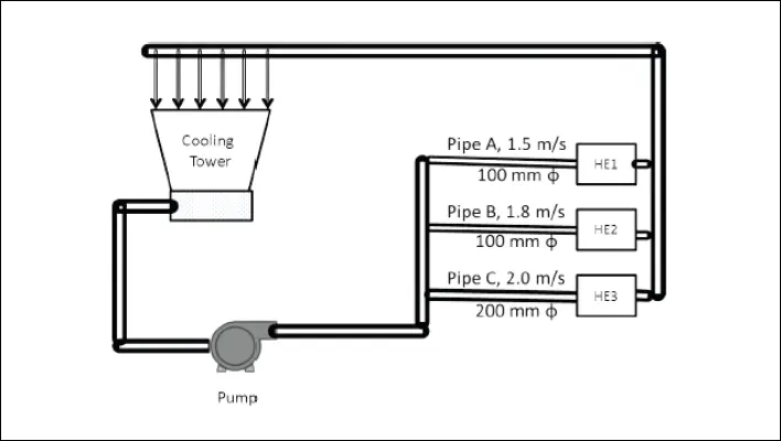
The following are the other data:
- Measured motor power : 50.7 kW
- Motor efficiency at operating load: 90%
- Pump discharge pressure : 3.4 kg/cm2
- Suction head : 2 meters
- Determine the efficiency of the pump
Let’s start by getting into the fundamentals of pumps and pump efficiency. This foundational knowledge will provide us with the necessary framework to grasp the problem statement more effectively.
Also Read: How to find 3-phase AC motor parameters? Energy Manager exam question.
What is a Pump?
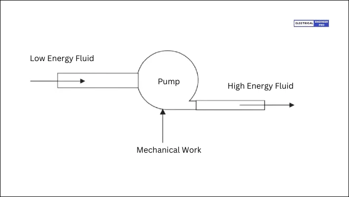
A pump is essentially a device that moves liquids by using mechanical power to boost the overall energy of the fluid.
Pumps find applications across various industries, including petroleum refineries, petrochemical plants, power stations, water desalination facilities, and pipelines for both water and oil transport.
A pump is designed to move liquid through a piping system and increase its pressure. It achieves this through a series of energy conversions.
At the start, an external energy source, such as electricity or steam, powers the pump’s driver. This input energy is converted into rotating mechanical energy, comprising the driver’s output shaft, rotating at a certain speed and transmitting torque.
Inside the pump, further energy transformations occur. The rotating shaft is connected to the impeller, a rotating component within the pump. As the impeller spins, it imparts kinetic energy to the liquid, increasing its velocity. This step involves the conversion of mechanical energy into kinetic energy, where the liquid’s mass and velocity play crucial roles.
Following the impeller stage, a diffusion process takes place. Here, the flow area expands, causing the liquid’s velocity to decrease. As velocity decreases, some of its kinetic energy is converted into pressure energy. This transformation raises the pressure of the liquid, allowing it to exit the pump at a higher pressure than when it entered.
In summary, a pump is a machine that utilizes energy transformations, primarily mechanical to kinetic and then to pressure energy, to move and pressurize liquids within a system.
Also Read: Energy Manager Exam | Co-generation power plant Numerical problem with solution
Types of Pumps
Pumps are available in various sizes to suit a broad spectrum of tasks. They can be categorized based on their fundamental operating principle as either dynamic or displacement pumps.
Dynamic pumps can further be divided into centrifugal and special effect pumps, while displacement pumps can be classified as rotary or reciprocating pumps.
In theory, any liquid can be handled by any pump design. However, when multiple pumps are designed to operate, centrifugal pumps are typically the most cost-effective option, followed by rotary and reciprocating pumps.
Despite positive displacement pumps generally being more efficient than centrifugal pumps, the advantage of higher efficiency is often counterbalanced by increased maintenance expenses.
Also Read: How to find apparent and reactive power of motor | Energy Manager exam question
Power Calculation for Pump
The electric motor needs power to rotate the shaft, which in turn drives the pump. This power requirement is determined by the flow rate that the pump must deliver and the pressure it needs to handle.
The work accomplished by a pump can be calculated by multiplying the flow rate of liquid pumped per unit time (expressed in cubic meters per sec) by the total head of the liquid in meters.
However, instead of using the weight of the liquid pumped, the pump’s capacity in cubic meters per sec and the specific gravity of the liquid are typically employed to determine the work done by the pump.
Output power
The output power (Pw) of the pump is termed Water Horsepower (WHP) or Hydraulic power, indicating the useful work output by the pump. The value of output power depends upon three factors; Flow, Head and Specific gravity of liquid.
Output Power (Pw) = Q X H X ρ X g
- Q = Flow rate in m3/sec
- H = Total Head (Discharge Head dh) – Suction Head ds) in (M) Meter Head.
- ρ = Specific Gravity in kg/m3
- g = Acceleration due to gravity in m/s2
Input power
The input power (Ps) of a pump represents the mechanical power consumed by the pump’s shaft or coupling, measured in kilowatts (kW) or watts (W). This input power is also referred to as Brake Horsepower (BHP) since it signifies the power delivered to the pump shaft, thus known as pump shaft power.
Also Read: Step-by-Step Guide to solve Energy Managers Exam Question on Motor Energy Savings
Pump Efficiency Formula
Pump efficiency is a measure of how effectively a pump converts input power into useful output power. It indicates the ratio of the pump’s output power (often hydraulic power or water horsepower) to its input power (typically shaft power or brake horsepower). Pump efficiency is usually expressed as a percentage, with higher percentages indicating greater efficiency.
Mathematically, pump efficiency (η) can be calculated using the formula:
[latex]Efficiency\% = \frac{Output Power (Pw)}{Input Power (Ps)}\times100[/latex]
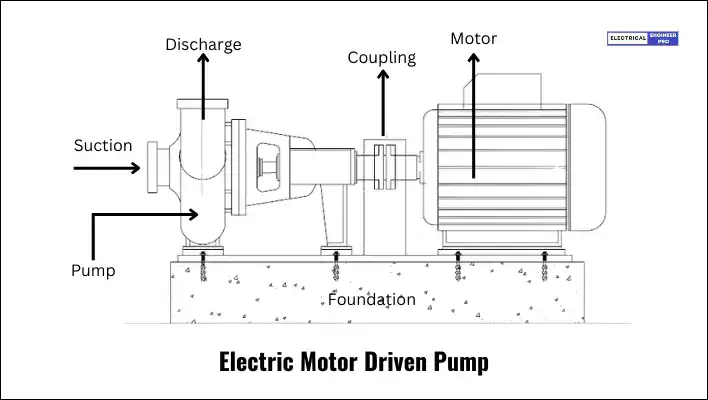
Pump Terminologies
Knowing the definitions and terminology used in the pumping system essential to solve the pumping related problem statements. The following are the basic definitions and terminologies to get a better understanding.
Flow Rate (Q)
Flow rate or Pump Capacity ‘Q’ is commonly used to express the actual volume flow rate delivered by the pump. Units of capacity include m3/s, ft3/s (cfs), gallons/minute (gpm), and barrels/day (BPD).
Total Head
The total head of a pump refers to the total energy imparted to the fluid by the pump. It represents the sum of the pressure head, velocity head, and elevation head of the fluid at the discharge point of the pump.
Discharge Head
The discharge head of a pump refers to the energy imparted to the fluid by the pump, specifically in terms of head (height) or pressure, as it exits the pump and enters the piping system. It represents the total head of the pump at the discharge point.
The pump discharge head is equivalent to the pump discharge pressure. Both terms refer to the pressure or head of the fluid at the discharge point of the pump.
Therefore, in many cases, the terms “pump discharge pressure” and “discharge head” are used interchangeably to describe the pressure or head of the fluid at the discharge point of the pump.
1 kg/cm2 = 10.00256 meter of head
Suction Head
The pump suction head, also known as the suction lift or suction head, refers to the total head (pressure or height) at the suction or inlet side of the pump. It represents the energy available to the pump at the point where it draws fluid into the pump.
Also Read: Energy Manager | Calculate Power Factor & Payback Period
Pump Efficiency Calculation
Solution to Energy manager Exam Problem
| Given Data: |
| Pipe A Dia 100 mm, Velocity – 1.5 m/s |
| Pipe B Dia 100 mm, Velocity – 1.8 m/s |
| Pipe C Dia 200 mm, Velocity – 2.0 m/s |
| Measured motor power : 50.7 kW |
| Motor efficiency at operating load: 90% |
| Pump discharge pressure : 3.4 kg/cm2 |
| Suction head : 2 meters |
| As discussed above the pump efficiency formula is expressed as, |
| [latex]Efficiency\% = \frac{Output Power (Pw)}{Input Power (Ps)}\times100[/latex] |
| The formula to find Output power which is also called Hydraulic power is, |
| Output Power Pw = Q X H X ρ X g |
| To determine the output power, we need to find the flow rate (Q) in each pipe and the total head (H) of the flow. |
| This involves determining the area of each pipe and multiplying it by the given velocities to calculate the flow rate in each pipe. |
| The formula to find area of pipe is, |
| [latex]Pipe Cross section Area =\frac{D^2}{4}\times3.14[/latex] |
Therefore, Flow rates in each pipe
| Flow Rate In Pipe A | [latex] =\frac{0.1^2}{4}\times3.14[/latex] |
| =0.00785 m2 | |
| Multiplying Pipe A Velocity | =0.00785 m2 x 1.5 m/sec |
| = 0.011775 m3/sec |
| Flow Rate In Pipe B | [latex] =\frac{0.1^2}{4}\times3.14[/latex] |
| =0.00785 m2 | |
| Multiplying Pipe B Velocity | =0.00785 m2 x 1.8 m/sec |
| = 0.01413 m3/sec |
| Flow Rate In Pipe C | [latex] =\frac{0.2^2}{4}\times3.14[/latex] |
| =0.0314 m2 | |
| Multiplying Pipe C Velocity | =0.0314 m2 x 2.0 m/sec |
| = 0.0628 m3/sec |
| Total Flow Rate (Q) | = 0.011775 + 0.01413 + 0.0628 |
| = 0.088705 m3/sec |
| Total Head (H) | = Discharge Head – Suction Head |
| Its given that the Pump discharge pressure is 3.4 kg/cm2. | |
| Pump discharge pressure is equivalent to Discharge head 1 kg/cm2 = 10 Meters of Head. | |
| Discharge Head | = 34 m |
| Therefore, Total Head (H) | = 34 – 2 |
| = 32 m |
Now calculating Output power of pump,
| Output Power (Pw) | = Q X H X ρ X g |
| Substituting the values for Q, H, ρ = 1, g = 9.81 | |
| = 0.088705 X 32 X 1 X 9.81 | |
| = 27.84 kW |
Finally, Pump Efficiency,
| Pump Efficiency | [latex] = \frac{Output Power (Pw)}{Input Power (Ps)}\times100[/latex] |
| Added Motor efficiency @ 0.9 to Input power. | [latex] = \frac{27.84}{50.7 \times 0.9}\times100[/latex] |
| = 61.01% |
Also Read:

