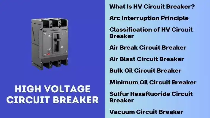
What is High Voltage Circuit Breaker?
High-voltage circuit breakers serve as switching devices designed to isolate faulty segments within expansive high-voltage power systems, ensuring the separation of compromised sections from the healthy ones. As a result, these devices play a crucial role in maintaining the integrity of the overall electrical power supply chain, safeguarding the transmission of mass electrical power from power plants to consumers.
The outlined definition states the significance of high-voltage circuit breakers in electrical power systems and can be further explained as follows.
- Switching Devices: High-voltage circuit breakers are specialized devices that have the ability to control the flow of electricity in a circuit. They can open or close the circuit, acting as switches in high-voltage environments.
- Fault Isolation: Their primary purpose is to identify and isolate faulty circuits within large high-voltage power systems. When a fault occurs in a specific section of the power network, the circuit breaker should quickly disconnect that portion from the rest of the system.
- Protecting Healthy Sections: By isolating the faulty circuits, these circuit breakers prevent the spread of electrical issues to other, unaffected parts of the system. This ensures that healthy sections continue to function without disruption.
- Crucial Role in Power Supply Chain: The definition emphasizes the important role of high-voltage circuit breakers in maintaining the integrity of the entire electrical power supply chain. The smooth operation of this chain is essential for the efficient transmission of electricity from power plants to end consumers.
- Safeguarding Transmission: The devices act as a protective barrier in the power transmission process. They safeguard the transmission of large amounts of electrical power from the generation source (power plants) to the end users (consumers). This protection is vital for the reliability and stability of the overall electrical grid.
In summary, high-voltage circuit breakers is a device which contributes significantly to the reliability and safety of high-voltage power systems by swiftly isolating and containing faults, thereby ensuring the continuous and secure transmission of electrical power to consumers.
Also Read: Smart Grid | The Ultimate Guide
Functions of High Voltage Circuit Breaker
High voltage circuit breakers main functions can be categorized into four key aspects, and they are also required to meet specific physical requirements:
- Switching-off Operating Currents: High-voltage circuit breakers are designed to interrupt the flow of normal operating currents, making it essential for routine maintenance, repair, or when electrical equipment needs disconnection from the power supply. This ability ensures a safe working environment for personnel and facilitates maintenance activities.
- Switching-on Operating Currents: In addition to interrupting current flow, HV circuit breakers must safely switch on operating currents. This function is vital when restoring power to a section of the system or connecting new equipment to the power grid. The circuit breaker must handle the initial surge of current during the re-closure without causing damage or overloading the system.
- Short-Circuit Current Interruption: During a fault, such as a short circuit, the circuit breaker must quickly and effectively open the circuit to prevent damage to equipment and ensure the safety of the power system.
- Secure Open and Closed Position: HV circuit breakers must securely maintain both open and closed positions. In the closed position, they should behave as good conductors to allow the flow of current. In the open position, they should act as good insulators to prevent current flow.
Apart from these main functions, HV circuit breakers must also fulfill specific physical requirements:
Fast Transition: HV circuit breakers must be capable of transitioning from the closed to the open position rapidly. This fast action is essential during fault conditions to minimize the duration of high fault currents and reduce the potential for damage.
No Over-voltages: During switching operations, HV circuit breakers should not generate over-voltages. Over-voltages can lead to insulation breakdown and damage to connected equipment. Ensuring a smooth transition during switching operations helps maintain the stability of the power system.
High Reliability: HV circuit breakers are expected to maintain high reliability during operation. This includes being ready for operation at any time, even after extended periods of non-operating time. Reliability is crucial to ensure the continuous and efficient functioning of the power system.
In summary, HV circuit breakers play a pivotal role in power systems, providing essential functions such as interrupting operating and fault currents, maintaining secure positions, and meeting specific physical requirements to ensure the reliability and safety of the electrical infrastructure.
Arc Interruption in High Voltage Circuit Breakers
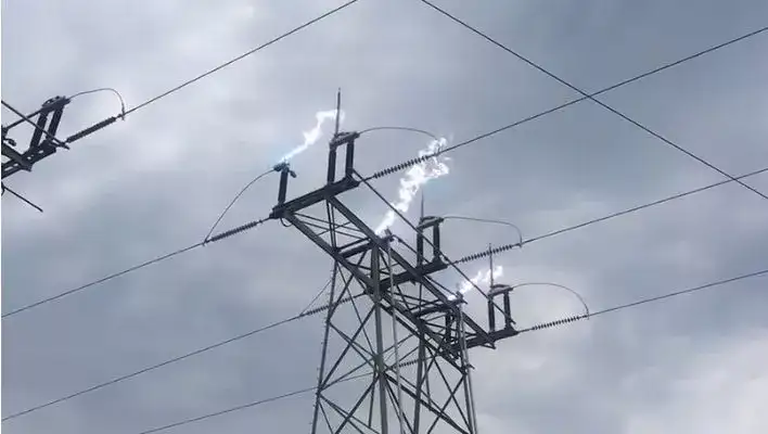
Arc interruption in high voltage circuit breakers is a fascinating yet critical aspect that we should understand, especially when it comes to AC circuit breakers.
The arc occurs in two ways during the separation of current-carrying contacts.
- When the circuit voltage is way below the minimum cold electrode breakdown level, arcs will be created. This is because ions neutralize the electronic space charge, allowing large currents to flow at relatively low voltage gradients. This happens in both AC and DC circuit breakers.
- The second way of arc occurrence is unique to AC circuit breakers only. In this kind, the arc gets extinguished every time the current hits zero. But re-strikes if the transient recovery voltage across the separating electrodes hits a high value during this process.
The most important role of an AC circuit breaker is to prevent this re-striking of the arc. And it depends on some important factors.
- The type and pressure of the arc’s medium
- The external agents mixed with ions
- The voltage across the electrodes and its variation with time;
- The material and shape of the electrodes
- The setup of the arcing chamber.
There are two methods of arc interruption:
- High Resistance Interruption
- Current Zero Interruption
High Resistance Interruption
In this technique of interrupting arcs, the resistance of the arc is increased to lower the current to a level insufficient for sustaining the arc. The resistance of the arc can be raised through methods such as cooling, elongating, restricting, and dividing the arc.
When the current is interrupted, the magnetic field’s stored energy converts into electrostatic energy, causing a high voltage to appear across the circuit breaker’s contacts. If this voltage exceeds the gap’s withstand capacity between the contacts, it may lead to the re-striking of the electrical arc.
As a result, this method is less suitable for interrupting high currents and is more appropriate for low-power AC and DC circuit breakers.
Current Zero Interruption
This method is specifically designed for AC circuit breakers. In AC power, the current changes direction 100 times per second at a frequency of 50 Hz. This unique AC feature is used to interrupt the arc.
The interruption is carefully timed to align with the zero-current moment, preventing the occurrence of a sudden high voltage across the contact gap. Thus, making sure the current doesn’t start rising again after hitting zero.
Also Read: Importance of Power Transmission Lines | Explained
How is induced Arc useful for current interruption in High Voltage Circuit breaker?
When two current-carrying contacts separate, the formation of an arc across the contact gap becomes a critical element in preventing an abrupt interruption of the current flow.
This arc serves a valuable purpose by establishing a low-resistance path for the current to follow after the contacts part ways. This functionality is essential in averting issues such as current chopping and abnormal switching over-voltages within the system.
Thus, It is crucial to recognize that the arc is not an undesirable phenomenon and plays a pivotal role in the process of current interruption.
Without the arc, the instantaneous interruption of current flow would occur, leading to the rapid collapse of the associated magnetic field. This, in turn, would induce very high voltages, placing considerable stress on the insulation of the system.
As a result, the arc facilitates a gradual yet expeditious transition from the current-carrying to the current-breaking states of the contacts. This feature allows disconnection to take place at zero current, mitigating the risk of inducing dangerously high voltage levels.
In light of these considerations,The significance of an arc-control device in a circuit breaker becomes apparent, as its primary function is to efficiently harness the beneficial action of the arc in the process of current interruption, ensuring a controlled and secure disconnection of the circuit
Circuit-Breaker Classification
Circuit breakers can be categorized based on various criteria, including intended voltage application, installation location, external design characteristics, and the insulating medium utilized for arc quenching.
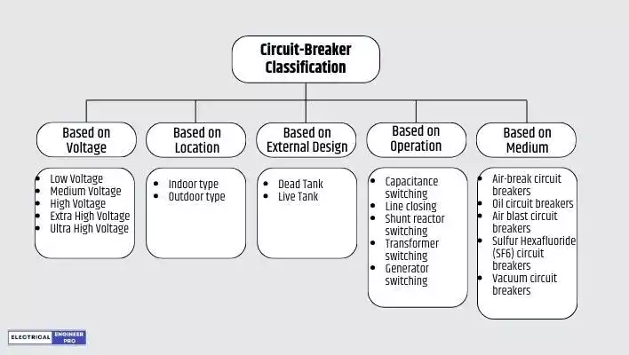
Classification Based on Voltage
- Low Voltage Circuit Breaker (less than 1 kV)
- Medium Voltage Circuit Breaker (1 kV to 52 kV)
- High Voltage Circuit Breakers (66 kV to 220 kV)
- Extra High Voltage (EHV) Circuit Breaker (300 kV to 765 kV)
- Ultra High Voltage (UHV) Circuit Breaker (above 765 kV)
Classification Based on Location
Circuit breakers based on their location are classified as
- Indoor type
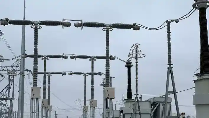
- Outdoor type
Indoor switchgears encompass low and medium voltage switchgears, as well as high voltage Gas Insulated Switchgears (GIS). On the other hand, outdoor switchgears are categorized as those with air serving as an external insulating medium, specifically referred to as Air-Insulated Switchgear (AIS).
Classification Based on External Design
Circuit breakers can be classified into following categories depending on their external design.
- Dead tank type: In dead tank circuit breakers, both the enclosures and interrupters (the components that open and close the circuit) are grounded and located at ground level.
- Live-tank type: In live tank circuit breakers, the interrupters are positioned above ground level, and they have the potential (are electrically live) even when the circuit is open.
This classification is for outdoor circuit breakers from the point of view of their physical structural design.
Circuit-breaker types by operation
The main purpose of HV circuit-breakers is interrupting abnormal conditions. Nevertheless, different applications of HV circuit-breakers must be taken into account. The applications of HV circuit-breakers can be classified as follows:
- Capacitance switching: capacitor banks and unloaded cable switching
- Line closing: overhead transmission line switching
- Shunt reactor switching
- Transformer switching
- Generator switching
Classification Based on Medium Used for Arc Quenching
Among the various methods of classifying circuit breakers, the primary and most crucial classification is based on the medium used for insulating and arc quenching. Depending on the arc quenching medium, important types of circuit breakers include:
- Air-break circuit breakers
- Oil circuit breakers
- Air blast circuit breakers
- Sulfur Hexafluoride (SF6) circuit breakers
- Vacuum circuit breakers
Also Read: Essential Guide to Voltage Unbalance
Types of High Voltage Circuit Breakers
Air-Break Circuit Breakers
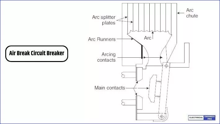
Air-break circuit breakers stand out as the ideal choice for effectively handling high-current interruption at low voltage levels. It utilizes air at atmospheric pressure as its arc extinguishing medium, setting it apart in terms of reliability and efficiency.
These circuit breakers, particularly in the AC variant, cover a voltage range from 400 to 12 kV.
At the heart of the air-break circuit breaker’s design are two pairs of contacts—main contacts and arcing contacts. The main contacts, characterized by low contact resistance, bear the current load when the breaker is in a closed position.
Upon opening, the main contacts separate first, transferring the current seamlessly to the arcing contacts. Later on, the arcing contacts separate, initiating the arc between them.
Air-break circuit breakers implement high-resistance principle for arc interruption by strategically lengthening, splitting, and cooling the arc. These breakers have arc runners and arc chutes which rapidly increase the arc length, while electromagnetic and thermal effects guide the arc upward. The arc is then directed into a chute, where arc splitters effectively split it.
The blow-out coil provides a magnetic field to accelerate arc movement and direct it into the arc splitters. Notably, the blow-out coil is intelligently activated automatically during the breaking process, enhancing the overall interruption process.
While deemed outdated for medium voltage applications, these circuit breakers remain the favored option for low voltage applications with high current ratings.
Bulk Oil-Volume Circuit Breakers
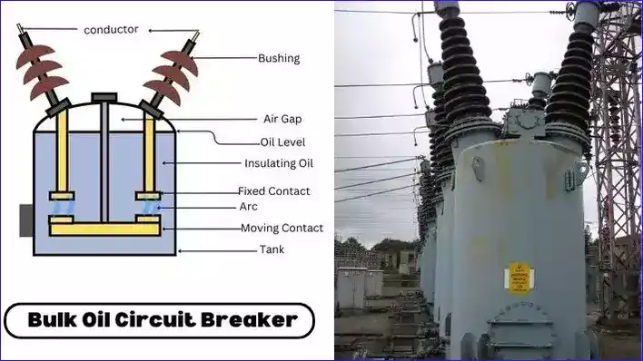
Bulk oil circuit breakers are characterized by the separation of contacts within oil and wherein the oil also provides the primary insulation between the live part and earthed metal tank.These circuit breakers are prevalent across a broad voltage spectrum, ranging from 1000 V to 330 kV.
Typically featuring a metal top dome, these circuit breakers incorporate six bushings passing through it to establish connections within the system. Arc control devices are generally attached to the lower ends of these bushings. The moving contacts are arranged on a bridge, fastened to an insulated drive rod, with a removable tank housing the insulating oil securely bolted to the dome.
In early designs of bulk oil circuit breakers adopted a double break configuration, incorporating two sets of contacts and arc control devices in series within each phase. However, challenges related to voltage division during the recovery period led to the evolution of single break designs by some manufacturers.
The operational principle relies on maintaining pressure generated by oil vaporization and dissociation within the pot. This is achieved by withdrawing the moving contact through a stack of insulating plates with minimal radial clearance. The pressure release occurs when the moving contact uncovers one of the side vents, created by cutting a slot in one of the plates.
The decomposition of oil during arcing produces hydrogen, acting as an insulating and highly thermally conductive gas. This crucial phenomenon plays a significant role in extinguishing arcs in bulk-oil circuit breakers.
Arc quenching is further enhanced by factors such as the turbulence of oil caused by arcing and the introduction of cool oil into an ionized medium.
Despite being considered outdated, these breakers serve as historical artifacts, reflecting the historical reliance on oil-based solutions in electrical systems.
Minimum Oil Volume Circuit Breakers (MOCB)
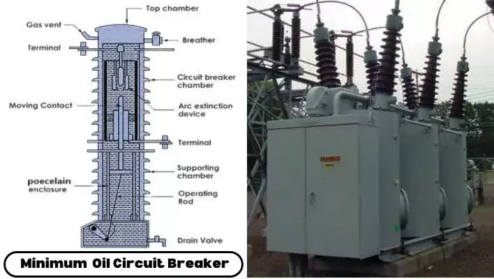
These Circuit breakers also utilize oil as the interrupting medium. However, they distinguish themselves from bulk oil circuit breakers by incorporating interrupting units within insulating chambers at live potential. This distinctive design characteristic, set them apart from their bulk oil counterparts which results in the nomenclature of Minimum Oil Circuit Breakers (MOCBs).
In contrast to bulk oil circuit breakers, MOCBs do not employ a steel tank. Instead, their container is crafted from porcelain or another insulating material.
Structurally, an MOCB comprises two distinct sections: an upper chamber and a lower chamber. The upper chamber houses the arc control device, featuring both fixed and moving contacts.
Meanwhile, the lower chamber serves as an insulating support, accommodating the operating mechanism. Although both chambers are filled with oil, they remain physically separated.
The arc control device resides within a resin-bonded glass fiber cylinder or a backelized paper enclosure, itself filled with oil. This assembly is then enclosed in a porcelain cylinder, with the annular space between the fiber-glass cylinder and the porcelain insulator which is also filled with oil.
Minimum oil circuit breakers are designed for a voltage range spanning from 3.3 kV to 420 kV. However, with advancements in technology, they have been superseded by SF6 circuit breakers in contemporary applications.
Air Blast Circuit Breakers (ABCB)

Air Blast Circuit Breakers (ABCBs) are a type of circuit breaker that uses compressed air at a pressure of 20-30 kg/cm2 to extinguish the arc during the interruption of the current. These circuit breakers are commonly used for voltage of 132 kV and above applications.
The fundamental principle behind air blast circuit breakers is to use a blast of compressed air to quench the electrical arc that forms when the circuit is interrupted.
An air-blast circuit breaker may be either of the following two types.
- Cross-blast Circuit Breakers
- Axial-blast Circuit Breakers
Cross-Blast Circuit Breakers
In cross-blast circuit breaker type, a high-pressure air blast is directed perpendicular to the arc to facilitate its interruption. The arc is forced into a designated chute, leading to a substantial elongation of the arc.
The extended arc length introduces significant resistance within the arc itself. That’s why, resistance switching is not a prevalent feature in these circuit breakers.
Cross-blast circuit breakers are particularly well-suited for interrupting high currents, reaching up to 100 kA, at relatively lower voltage levels.
Axial-Blast Circuit Breakers
Axial blast circuit breakers are well-suited for Extra High Voltage (EHV) and Ultra High Voltage (UHV) applications. In this type of circuit breaker, a high-pressure air blast is directed longitudinally, aligning with the arc.
To mitigate transient over-voltages, resistance switching is implemented. The number of breaks is dependent on the system voltage; for instance, there are four breaks at 220 kV and eight breaks at 750 kV.
This use of forced air for arc extinction (via a forced blast mechanism), has made this type of circuit breaker widely favored. Its popularity led to it gradually replacing MOCBs. The technology has evolved, and now there are designs for air-blast circuit breakers capable of handling voltages up to 735 kV.
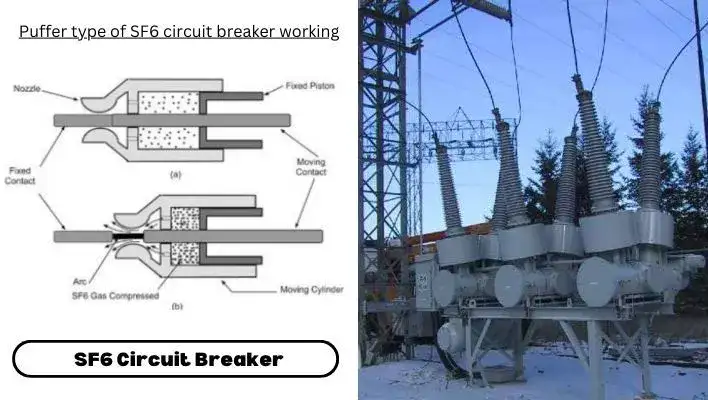
SF6 (Sulfur Hexafluoride) Circuit Breakers
An SF6 circuit breaker is a device where the contacts open and close within sulfur hexafluoride (SF6) gas. These circuit breakers are used for medium and high voltage applications, ranging up to 800 kV and beyond.
SF6, the gas used in these circuit breakers, possesses excellent dielectric strength and effective arc-quenching properties. It is a non-reactive, non-toxic, non-flammable, and dense gas.
At atmospheric pressure, its dielectric strength is approximately 2.35 times that of air, and even more than transformer oil at 3 atmospheric pressure.
In SF6 circuit breakers, the gas flows from a high-pressure zone to a low-pressure zone through a specially designed nozzle. The flow rate is influenced by the nozzle-throat diameter, pressure ratio, and duration of flow.
The nozzle is strategically placed so that the gas travels axially over the length of the electrical arc. In the divergent part of the nozzle, the gas accelerates to almost supersonic speed, drawing heat away from the arc’s periphery and causing a reduction in the arc’s diameter.
Ultimately, at the point of current zero, the arc diameter becomes nearly zero, thus extinguishing the arc.
Once the contact space is replenished with fresh SF6 gas, the dielectric strength quickly recovers due to the electronegativity of the gas and the turbulent flow of the fresh gas in the contact space.
There are two principal types of SF6 circuit breakers:
(i) Double Pressure Type SF6 Circuit Breaker: This type employs a double-pressure system where gas from a high-pressure compartment is released into a low-pressure compartment through a nozzle during the arc extinction process. However, this type has become obsolete.
(ii) Puffer-type (Single-pressure Type) SF6 Circuit Breaker: In this design, SF6 gas is compressed by the moving cylinder system and released through a nozzle during arc extinction. This is the more prevalent design for SF6 circuit breakers across a wide voltage range from 3.3 kV to 765 kV.
SF6 circuit breakers have gained widespread popularity due to their exceptional dielectric strength recovery rate. In fact, in contemporary installations, SF6 breakers are the preferred choice for voltage ratings ranging from 11 kV (or even 6.6 kV) up to an impressive 735 kV.
The gradual phasing out of air-blast circuit breakers is evident as SF6 technology continues to dominate. Furthermore, SF6 enclosed indoor metal-clad switchgears are increasingly favored in various applications, reflecting the growing prominence of SF6 circuit breakers in the field of electrical power systems.
Also Read: What is interconnected power system or grid?
Vacuum Circuit Breakers (VCB)
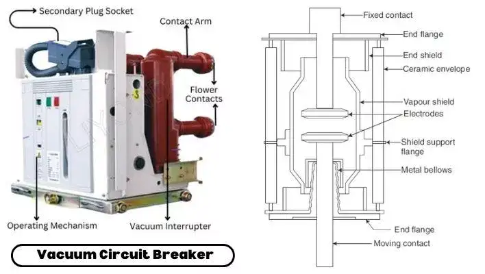
A vacuum circuit breaker is a special kind of circuit breaker where the process of stopping the electric arc occurs in a vacuum instead of other mediums.
The strength of high vacuum, in terms of its ability to resist electricity and interrupt arcs, surpasses that of materials like porcelain, oil, air, and even SF6 at normal atmospheric pressure.
In the design of a vacuum interrupter, there’s a central steel arc chamber and symmetrically arranged ceramic insulators. Modern versions also incorporate a metal shield around the arcing contacts.
The sizes of the contacts, stems, arc chamber, and insulators are carefully matched. The moving contacts are made adjustable using metallic bellows. The arc chamber is welded to housing flanges, which are brazed to metallized ceramic insulators, ensuring a tightly sealed interrupter. The vacuum pressure inside is generally maintained at 10-6 bar.
Compared to other types of circuit breakers, the vacuum circuit breaker boasts simplicity in construction. The separation between contacts is about 1 cm, which proves sufficient for interrupting current in a vacuum.
Due to its compact design, the power needed to open and close its contacts is considerably less than other breakers. Moreover, it can interrupt capacitive and small inductive currents without causing excessive transient over-voltages.
The vacuum circuit breaker (VCB) is widely acknowledged today as the most reliable option with the least maintenance requirements among all available technologies for controlling and safeguarding distribution circuits. It is commonly believed worldwide that the VCB will be the predominant medium voltage technology in the twenty-first century.
FAQs
What is digital testing of high voltage circuit breakers?
The assessment of high-voltage circuit breakers through digital testing involves a specialized software created by leading manufacturing companies. This software is designed to test a specific model of high-voltage circuit breaker, to extract its characteristics from precise measurements obtained during standard tests. Digital testing opens up a myriad of opportunities for users, manufacturers, standardization bodies, and test laboratories, enabling the fine-tuning of circuit breaker capabilities to align with both industry standards and real power system requirements.
Why is digital testing important for high-voltage circuit breakers?
Digital testing allows for a more comprehensive evaluation of high-voltage circuit breakers. It involves using specialized software to analyze specific models, extracting unique characteristics and fine-tuning capabilities to align with industry standards and real power system requirements.
Where are high-voltage circuit breakers commonly used?
High-voltage circuit breakers find application in various industries, including power generation, transmission, and distribution. They are crucial for protecting transformers, generators, and other high-voltage equipment from faults and over-currents.
Are high-voltage circuit breakers used in renewable energy systems?
Yes, high-voltage circuit breakers are essential components in renewable energy systems, such as wind and solar power plants. They protect the electrical infrastructure and ensure the safe and reliable operation of these systems.
What are the environmental considerations of high-voltage circuit breakers?
Some circuit breakers use environmentally sensitive insulating gases like SF6. It’s important to consider the environmental impact of these gases and explore alternatives with lower global warming potential to minimize their contribution to climate change.
Can we use AC high-voltage circuit breakers in DC High Voltage power transmission?
No, AC-designed circuit breakers cannot be utilized in DC applications due to the unique nature of DC, rendering them ineffective and potentially harmful to the system.