The article was posted by Vishal Shere on LinkedIn.
In electrical installations, one often encounters debates surrounding the necessity of separate earth electrodes for equipment such as DG sets and transformers.
Electrical inspectors frequently demand the installation of two separate and distinct earth electrodes for DG sets and transformers, citing safety concerns and regulatory compliance.
Yet, a closer examination reveals that such mandates may not always align with established standards like the IS 3043, Central Electricity Authority (CEA) regulations and Indian Electricity Rules (IE rules).
Despite the absence of explicit requirements in the aforementioned regulations, inspectors often insist on separate earth electrodes for each equipment. The explanation for this insistence lies in the misinterpretation of standards and guidelines.
Electrical inspectors may argue that separate earth electrodes reduce the risk of fault propagation and enhance the overall safety of electrical systems. However, this argument overlooks the comprehensive safety measures already mandated by existing regulations.
Also Read: Discover the Top Earthing Essentials: Types, Parts & Purpose
Understanding the Regulations
To accurately address this matter, it’s essential to consult relevant regulations and codes. Standards such as IS 3043, CEA regulations, and IE rules serve as foundational documents for safety measures in electrical installations. These guidelines are not only referenced by electrical inspectors but also by MEP consultants and engineers involved in electrical installation work.
IS 3043
Let’s examine what Indian Standard 3043 states regarding separate and distinct earth electrodes.
IS3043 section 4 clause no 4.2 says,
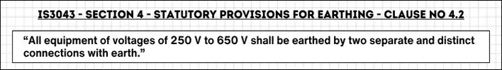
The part of clause “earthed by two separate and distinct connections with earth” is often misconstrued and mistakenly assumed to be earth electrodes in soil.
The key point to understand is that, the phrase “connections with earth,” does not refer to electrodes in the soil; rather, it denotes any means of connection to the earth grid.
Similarly, terms like “earthed” and “earthing systems” also signify being connected to this grid.
In essence the regulation stipulates that the body and neutral must have two connections to the (earth) earthing system and not to the two separate and distinct earth electrodes.
Also Read: Types of High Voltage Circuit Breakers | Explained
Central Electricity Authority (CEA) regulations
Central Electricity Authority (CEA) is a statutory body assisting the ministry of power in all technical and economic matters. It is primarily responsible for setting up technical standards and regulations for the power sector.
Below picture shows the excerpts from CEA notification Part 3, section 4, Chapter V, released in June 2023.
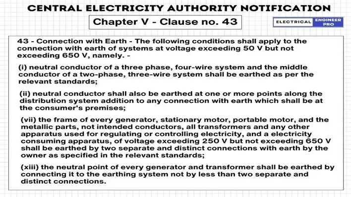
The correct interpretations of the clauses are as follows:
- Clause (i) specifies that the neutral conductor, not the neutral point, must be grounded according to relevant standards, which is IS 3043.
- Clause (ii) confirms that along the distribution lines at consumer premises, it is the neutral conductor, not the neutral point, that needs to be earthed.
- Clause (vii) stipulates that the metallic frame of every generator and metallic parts, not intended as conductors, should be grounded by two separate and distinct connections with the earth, not with two separate and distinct earth electrodes.
- Clause (xiii) clarifies that the neutral point, not the neutral conductor, must be connected by at least two separate and distinct connections with the earthing system, not with two separate and distinct earth electrodes.
These interpretations highlight that according to the regulations, the body of transformers (or DG sets) should be connected to earth, not necessarily to separate earth electrodes in the soil.
The regulation does not recommend connecting the neutral and body of transformers (or DG sets) to separate earth pits. Any practice following this approach is simply a misinterpretation of the regulation.
Also Read: What is interconnected power system or grid?
Indian Electricity Rules, 1956.
The following rules mentioned in the picture are extracted word to word from IE rules,
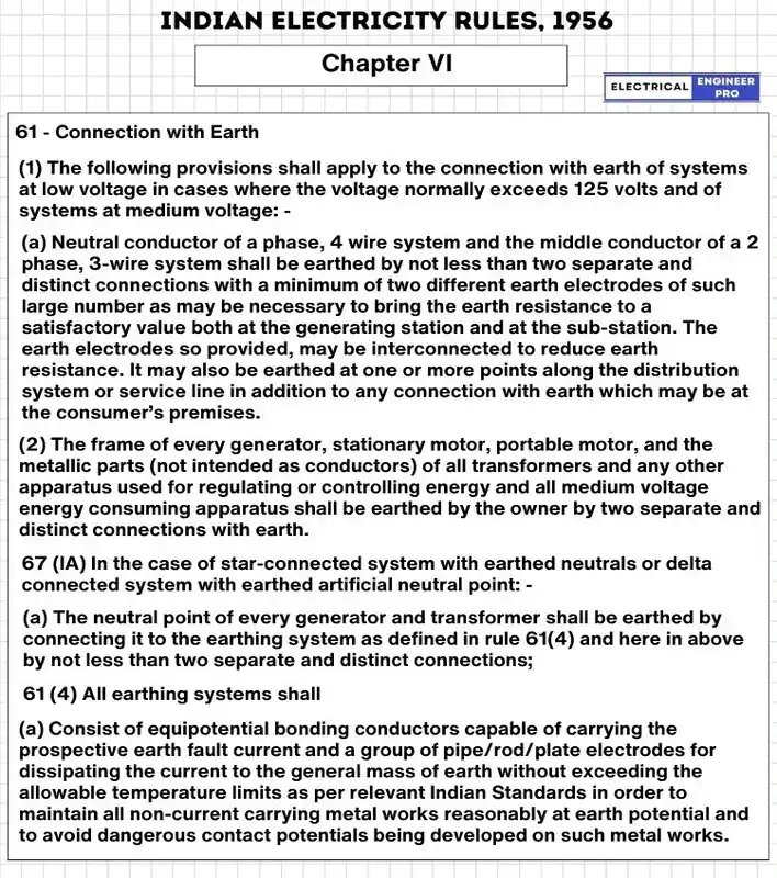
Upon reviewing the above, we understand that IE rules, CEA regulations and IS 3043 are in concurrence with each other. Let asses each IE rule,
- From 61.1.a, it is confirmed that neutral conductor and not neutral point needs to be earthed with separate and distinct connection and not with two separate and distinct earth electrodes.
These neutral conductor connections must be made to a minimum of two different or more earth electrodes which shall be connected to each other, so the earth resistance value can decrease to acceptable levels. This statement does not mean that the neutral point is to be connected to two separate and distinct earth electrodes.
- Rule no 61.2 says the same as CEA regulation that all connections of body frames of equipment to be connected to two separate and distinct connections with earth.
- Rule 67 (lA) states that all the neutral points of DG or transformer shall be carried out as per rule no. 61(4).
- Rule 61(4) stipulates equipotential bonding of all conductors within the electrical installation, to avoid dangerous touch potential being developed on equipment enclosures.
Also Read: Importance of Power Transmission Lines | Explained
Difference between Neutral Point and Neutral conductor
The terms “neutral point” and “neutral conductor” refer to different concepts:
Neutral point: In electrical systems, the “neutral point” refers to the connection point of transformer or generator windings where the voltage to ground is typically zero. It’s commonly utilized for system groundings in Wye-connected AC power systems.
Neutral conductor: A “neutral conductor” is a wire that is connected to or intended to be connected to the neutral point of an electrical system. Its purpose is to assist in carrying energy within the system.
What Two Separate and Distinct Earth Electrodes actually mean?
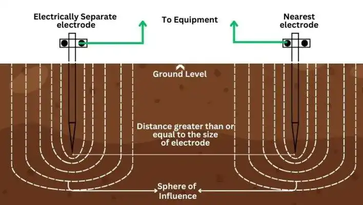
The phrase “two separate and distinct earth electrodes” refers to electrically independent earth electrodes which are interconnected, and are positioned at a significant distance from neighboring electrodes.
This arrangement prevents fluctuations in electrical potential between the electrodes, with the specified distance extending beyond the influence of nearby electrodes, a region often referred to as the “sphere of influence.”
The “sphere of influence” signifies the importance of spacing parallel earth electrodes properly to reduce ground resistance. The distance between these electrodes should be equal to or exceed electrode length.
However, “separate and distinct earth electrodes” is misconceived as an earth electrode that is exclusive to specific equipment such as DG sets, transformers and Lightning Arrestor, detached from the common earth grid.
This wrong notion emerged from the belief that interconnecting all earth electrodes may lead to equipment damage during sudden surges of ground fault currents.
Electronic and Instrumentation engineers, in particular, tend to support this notion, advocating for separate earth electrodes for their equipment.
Also Read: Essential Guide to Voltage Unbalance
Drawbacks of Two Separate and Distinct Earth Electrodes
Having two separate and distinct connections to earth electrodes in an electrical system can lead to several disadvantages:
- Having two connections to earth electrodes can make protective devices malfunction during faults. This prevents the faulty section from being isolated, leading to dangerous situations like electric shocks or fires.
- Two separate earth electrodes can create ground loops, which are unintended current paths that can introduce noise and interference into sensitive electronic circuits. Ground loops can degrade the performance of electrical and electronic systems.
- Some standards and regulations specify requirements for a single, integrated grounding system. Having two separate earth electrodes may not comply with these requirements, leading to non-compliance issues and potential legal or regulatory consequences.
- Non standard earthing practices cause rise in power frequency to withstand voltages, compromising the safety and reliability of the electrical system, increasing the risk of electrical accidents and equipment damage.
- Inconsistent and non-standard practices in electronic systems can greatly affect their performance, leading to malfunctions and reduced reliability in electronic equipment.t.
Correct way of Earthing
Equipotential bonding and automatic disconnection of supply are implemented to safeguard against earth faults and leakage, ensuring that touch voltages do not persist long enough to pose a threat to human safety.
The event of Earth fault results in two hazards,
- When there’s an earth fault in an electrical setup and exposed wires touch metal parts that shouldn’t be touched, it creates a shock hazard. This situation, known as indirect contact, can be dangerous if those parts are easy to reach at the same time.
- The current that flows through the wires of a circuit supplying faulty equipment, especially when there’s an earth fault in the wiring itself, can become so strong that it heats up the wires excessively. This overheating poses a risk of starting a fire.
Equipotential bonding and automatic disconnection of supply is a protective measure against both of these hazards which ensures that touch voltages do not persist long enough to pose a threat to human safety.
Automatic Disconnection of Supply
Automatic disconnection is meant to stop touch voltage from lingering long enough to become dangerous. This requires coordination between the system earthing and protective devices used in the installation.
For automatic disconnection of the power supply, protective equipotential bonding is recommended in IS 3043. It also advocates connections of extraneous-conductive parts to the main earthing terminal of the installations by equipotential bonding conductors.
Also Read: Power Supply System | A Comprehensive Guide
Equipotential Bonding
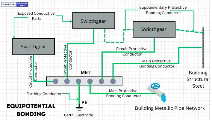
Equipotential bonding is the practice within a system whereby all exposed conductive components, such as metal frames of active equipment and equipment bodies, as well as extraneous conductive elements like metallic items embedded in building concrete and metallic pipelines, are interconnected with the main earthing terminal.
This ensures that they are all maintained at the same potential in the event of an earth fault, thus promoting safety and preventing electrical hazards.
IE Rule 61(4) stipulates equipotential bonding of all conductors within the electrical installation, to avoid dangerous touch potential being developed on equipment enclosures.
Right practice of Earthing
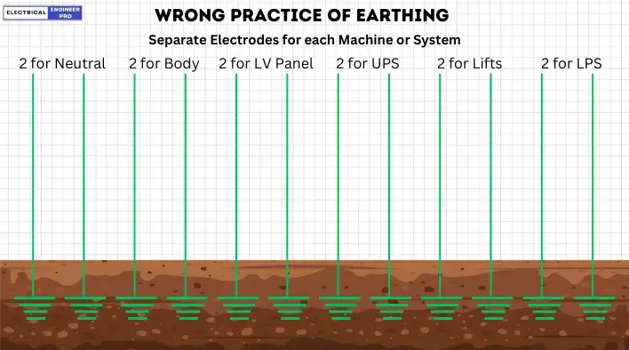
Separate electrodes for each equipment creates accidents, Insulation failure, less life and malfunction of electrical/electronic equipment.
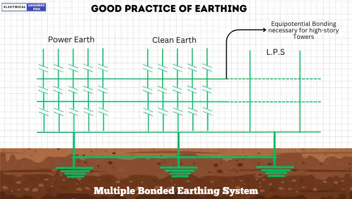
Connecting all earthing conductors and earth electrodes to create an equipotential bonding among all for safe and maximum life of electrical and electronic system is good practice of earthing.
Moving forward…
In light of these observations, there is a pressing need for clarity and consensus regarding the requirements for earth electrodes in electrical installations.
European countries have embraced the Global Earthing System, whereas in India, there remains a demand for separate earth electrodes for DG sets and transformers from electrical inspectors. Therefore, it is imperative to critically evaluate the reasoning behind such mandates.
Harmonizing regulatory interpretations and promoting adherence to established standards can streamline inspection processes and foster greater confidence in the safety and reliability of electrical systems.
All stakeholders, including regulatory bodies, industry professionals, and electrical inspectors, must engage in constructive dialogue to address these discrepancies for safer, more efficient electrical installations.