Electrical systems play a crucial role in our daily lives, it’s crucial to grasp the concept of voltage unbalance and its significance in maintaining the integrity of electrical systems and equipment. Voltage unbalance occurs when the magnitudes of the three-phase voltages in a system are unequal.
In this article, we will explore the definition of voltage unbalance, its impacts on electrical systems, the formula for calculating voltage imbalance, causes of voltage unbalance, effects on various electrical equipment, practical strategies for mitigation, and the importance of voltage balance in engineering practices.
Also Read: Types of High Voltage Circuit Breakers | Explained
What is Voltage Unbalance?
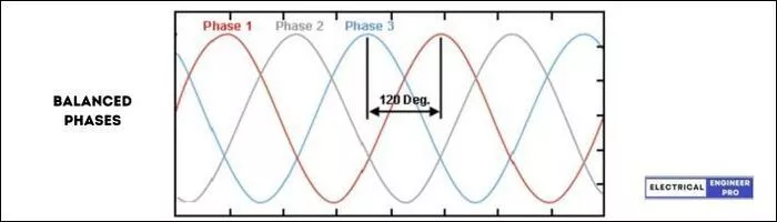
In a well-functioning electrical system, it’s important for the three phases of electricity to work together smoothly, like a synchronized dance.
The voltages of these three phases should work in harmony with each other. They should have the same magnitude and maintain a separation angle of 120 degrees from each other.
This balanced arrangement ensures that electrical equipment and devices can function without any hiccups.
But sometimes, there are moments when the voltages of the three phases become unequal in magnitude or deviate from the desired 120-degree phase separation.
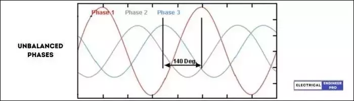
When this happens, we call it an “Voltage Unbalance.” It’s like the electrical system is throwing a tantrum and refusing to cooperate.
Voltage unbalance can happen due to various reasons.
One reason is the variation in the characteristics of the electrical lines used for transmitting and distributing electricity. These lines may have differences in their properties, such as resistance or impedance, leading to unequal voltages.
Another culprit is the uneven distribution of electrical loads across the three phases.
If one phase is burdened with a greater number of electrical devices drawing power compared to the other phases, it can result in unbalanced voltages.
Voltage unbalance should be addressed on priority because it can have detrimental effects. It can lead to issues like overheating, reduced efficiency and even damage to motors, equipment and sensitive electronics.
By identifying and resolving the culprits behind the unbalance, we can restore order and bring back a stable and reliable power supply.
This means our electrical systems and devices can go back to working efficiently, staying protected, and enjoying a longer lifespan. It’s like restoring peace and harmony to the electrical dance floor.
Also Read: Power Supply System | A Comprehensive Guide
Definitions of Voltage Unbalance Factor
Voltage unbalance can be measured using a term called the voltage unbalance rate (VUR), which is usually given as a percentage. The VUR tells us how much the voltage in a system is unbalanced.
Different organizations have different ways of defining the voltage unbalance factor.
The National Electrical Manufacturer Association (NEMA) and the International Electrotechnical Commission (IEC) have popular and widely used definitions.
Here are the definitions of voltage unbalance factor from various sources:
Definition of voltage unbalance rate (VUR) as per NEMA
The voltage unbalance in percent is defined by the National Electrical Manufacturers Association (NEMA) in Standards Publication no. MG 1-1993 as
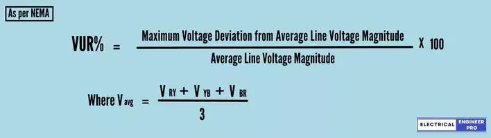
The NEMA definition assumes that the average voltage in the system is always equal to the rated value and that rated value is typically 480 V for three-phase systems.
This definition focuses only on the magnitudes of the voltages and does not consider the phase angles between them.
Definition of voltage unbalance rate (VUR) as per IEEE
According to the IEEE standard 141, the Voltage Unbalance Rate (VUR) is defined in the same way as the NEMA definition. The only difference is that instead of using line voltages, the phase voltages are considered. Thus, it is also referred to as the Phase Unbalance Voltage Rate (PVUR).
So as per IEEE definition,
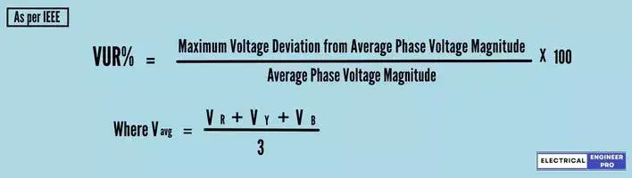
The definition provided by IEEE cannot be applied to angle unbalanced situations. As a result, this particular definition is rarely utilized by researchers and field engineers.
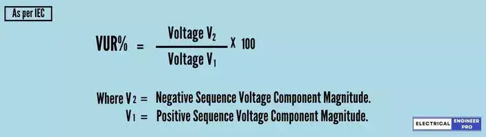
Definition of voltage unbalance rate (VUR) as per IEC
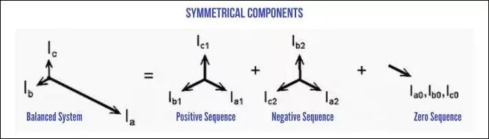
Symmetrical components can be used to describe unbalanced voltages. The definition of Voltage Unbalance Rate (VUR), which is often regarded as the ‘True’ definition of voltage unbalance, relies on comparing the magnitudes of the negative and positive sequence voltages.
The VUF definition adopted by the IEC is,
These definitions help us understand and quantify the level of voltage unbalance in a system. By using the voltage unbalance rate, we can assess the extent of the voltage unbalance and take appropriate measures to address it.
Causes of Voltage Unbalance
Here are some common causes of unbalanced voltages, explained in bullet points for beginners:
- Unbalanced incoming utility supply: When the power supply from the utility company is unevenly distributed among the phases.
- Unequal transformer tap settings: If the taps on a transformer are not set equally, it can lead to imbalanced voltage output.
- Large single-phase distribution transformer on the system: A single-phase transformer that is significantly larger than others in the system can cause voltage imbalances.
- Open phase on the primary of a 3-phase transformer on the distribution system: If one of the primary phases of a 3-phase transformer is not functioning properly, it can lead to voltage imbalances.
- Phase to phase or grounds faults in the power transformer: Issues like faults or grounding problems in the power transformer can cause voltage imbalances.
- Open delta connected transformer banks: In a system where transformers are connected in an open delta configuration, imbalances can occur if one transformer is not functioning.
- A blown fuse on a 3-phase bank of power factor improvement capacitors: If a fuse in a bank of capacitors used for power factor improvement blows, it can result in voltage imbalances.
- Unequal impedance in conductors of power supply wiring: When the impedance of the conductors carrying the power supply is not equal, it can lead to voltage imbalances.
- Unbalanced distribution of single-phase loads such as lighting: If single-phase loads, like lighting fixtures, are not evenly distributed across the phases, it can cause voltage imbalances.
- Heavy reactive single-phase loads such as welding machines: Single-phase loads that draw a significant amount of reactive power, like welders, can contribute to voltage imbalances.
Also Read: Understanding Conventional Power Plants – A Detailed Exploration
Impacts of Voltage Unbalance
Voltage unbalance can have significant repercussions on electrical systems and equipment. Some common impacts include:
- Overheating: Voltage unbalance causes unequal distribution of power among the three phases, leading to excessive heat generation in electrical devices. This can result in increased wear and tear, decreased efficiency, and even complete equipment failure.
- Motor Malfunction: Unbalanced voltages can negatively affect the performance of electric motors. It leads to uneven torque production, increased motor currents, reduced efficiency, and, in severe cases, motor overheating and damage.
- Reduced Equipment Lifespan: Continuous exposure to voltage unbalance can significantly decrease the lifespan of electrical equipment. The uneven distribution of electrical stress and heat places additional strain on components, resulting in premature failure and increased maintenance costs.
- Light Flickering: Voltage unbalance can cause flickering or fluctuation in lighting systems, leading to discomfort and potential safety hazards.
- Poor Power Factor: Voltage imbalances can result in poor power factor, which can lead to penalties imposed by utility companies. Low power factor also reduces the efficiency of electrical systems.
Voltage Unbalance Standards
Regrettably, there exist various standards that establish different acceptable thresholds for voltage unbalance. Here are some of the standards that are published by International Organizations which are related to electrical technology,
As per NEMA
The National Equipment Manufacturers Association (NEMA) represents companies that make motors and drives. According to their guidelines (NEMA MG-1-1998), motors are expected to work properly even if there is only a 1% difference in voltage.
NEMA MG-1 says that a 1% voltage difference can cause a current difference of 6-10%.
The 1% limit set by NEMA is more strict than the recommendations of other international standards organizations responsible for creating and publishing global standards for electrical, electronic, and related technologies.
As per ANSI
The American National Standard for Electric Power Systems and Equipment, known as ANSI C84.1, advises that electric supply systems be designed and operated in a way that restricts the maximum voltage unbalance to 3%.
In other words, the standard advises maintaining a voltage unbalance of no more than 3% to ensure the proper functioning of the electric power system.
As per IEC
IEC 60034-1 imposes a maximum limit of 1% for negative phase sequence voltage in the power supply provided to machines.
To elaborate, a three-phase alternating current (a.c.) motors should be able to operate effectively on a three-phase voltage system.
This voltage system should have a negative-sequence component that remains within 1% of the positive-sequence component over an extended period of time.
However, for a short duration, not exceeding a few minutes, the negative-sequence component can be up to 1.5%.
Additionally, the zero-sequence component should not exceed 1% of the positive-sequence components.
These requirements ensure that the motors can handle the different components of the voltage system and perform reliably.
As per EN 50160
EN 50160 states that, during regular operation, over the course of one week, it is required that 95% of the 10-minute average root mean square (rms) values of the negative phase sequence component of the supply voltage fall within the range of 0 to 2% of the positive phase sequence component.
In certain areas where there are installations with users connected to partially single-phase or two-phase networks, unbalances of up to approximately 3% at the three-phase supply terminals may occur.
Such inconsistencies in standards can result in disagreements among customers, motor manufacturers and utility providers. So it is important to thoroughly examine the service guidelines of the utility and the guidelines provided by the motor manufacturer to prevent potential conflicts.
Also Read: Smart Grid | The Ultimate Guide
Calculating Voltage Unbalance
To quantify voltage unbalance, engineers use the concept of voltage unbalance rate (VUR). VUR is a ratio that compares the deviation of the highest voltage from the average voltage to the average voltage itself. The formula to calculate VUR is as follows:
VUF = (Vmax – Vavg) / Vavg
Vmax represents the highest voltage among the three phases, and Vavg represents the average voltage.
Here’s an Example,
| Assume the following Phase-Phase voltages were measured, | |
| R-Y | 480 volts |
| Y-B | 473 volts |
| B-R | 451 volts |
| Average Voltage (Vavg) | [latex]Vavg = \frac{480 + 473 + 451}{3}[/latex] |
| [latex]Vavg = 468 volts[/latex] | |
| Maximum Voltage Deviation from Average (Vmax) | [latex]Vmax = {468 – 451}[/latex] |
| [latex]Vmax = 17 volts[/latex] | |
| Voltage Unbalance Rate (VUR) % | [latex]VUR\% = \frac{17}{468}\times 100[/latex] |
| [latex]VUR = 3.6\%[/latex] |
Mitigation Strategies for Voltage Unbalance
To mitigate voltage unbalance and its associated effects, engineers employ various strategies. Here are some practical measures:
- Load Balancing: Properly distribute single-phase and three-phase loads across all phases to ensure balanced current and voltage. This approach helps minimize voltage imbalances and ensures optimal performance.
- Transformer Selection: Choose transformers with appropriate ratings and tap configurations to mitigate voltage imbalances. Transformers with multiple taps allow for adjustments to correct any voltage deviations.
- Power Quality Monitoring: Implement power quality monitoring systems to continuously assess voltage levels and detect any deviations or imbalances. These systems provide valuable data for troubleshooting and corrective actions.
- Harmonic Filters: Install harmonic filters to mitigate voltage unbalance caused by non-linear loads. These filters help reduce harmonics and maintain balanced voltages.
- Regular Maintenance: Scheduled maintenance and inspection of electrical equipment are essential to identify and rectify potential issues that can lead to voltage unbalance. Regular testing of transformers, motors, and other critical components can ensure their optimal performance and prevent unbalance-related problems.
- Voltage Regulation: Installing automatic voltage regulators (AVRs) or static voltage regulators (SVRs) can help stabilize and regulate the voltage levels within acceptable limits, minimizing the chances of voltage unbalance.
Also Read: Importance of Power Transmission Lines | Explained
Conclusion
Voltage unbalance is a critical aspect of electrical and mechanical engineering that directly affects the performance and lifespan of electrical systems and equipment. By understanding the causes, effects, and mitigation strategies associated with voltage unbalance, engineers can ensure the reliability, efficiency, and longevity of electrical systems.
Proper load balancing, transformer selection, power quality monitoring, and the use of harmonic filters are essential tools in combating voltage unbalance. Remember, maintaining voltage balance is key to optimal performance and cost-effective operations in electrical engineering.