Flywheel energy storage systems (FESS) are a great way to store and use energy. They work by spinning a wheel really fast to store energy, and then slowing it down to release that energy when needed.
FESS are perfect for keeping the power grid steady, providing backup power and supporting renewable energy sources. They’re quick, efficient, and help make our energy supply more reliable. Want to know more about FESS? Keep reading!
Also Read: Energy Storage System | Key Technologies Explained
Flywheel as Energy Storage
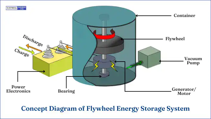
A flywheel operates on the principle of storing energy through its rotating mass. Think of it as a mechanical storage tool that converts electrical energy into mechanical energy for storage. This energy is stored in the form of rotational kinetic energy.
Typically, the energy input to a Flywheel Energy Storage System (FESS) comes from an electrical source like the grid or any other electrical source. As the flywheel stores energy, it speeds up, and when it discharges, it slows down to release the stored energy.
To make this happen, a motor-generator (MG) unit drives the rotating flywheel, converting electrical energy to mechanical energy, and vice versa. They’re connected in a way that controlling the MG also controls the flywheel’s operation.
Flywheels boast several qualities that make them handy for various applications:
- They have a high power density, meaning they can release a lot of energy in a small space.
- They also have a high energy density, packing a punch in terms of the amount of energy they can store.
- Unlike some other storage systems such as batteries, flywheels don’t degrade over time based on how deeply they’re discharged or how often they’re used.
- Monitoring the state of charge is straightforward with flywheels since it’s directly related to the rotational velocity.
- They require little to no maintenance, saving time and effort.
- Flywheels recharge quickly, making them ready for action in a short amount of time.
- The technology is scalable and adaptable, making it versatile and widely applicable.
- Plus, they’re environmentally friendly, using materials with a low impact on the environment.
Also Read: Biomass Energy Explained | Resources, benefits & Tech
Flywheel Energy Storage Working Principle
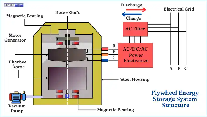
Flywheel Energy Storage Systems (FESS) work by storing energy in the form of kinetic energy within a rotating mass, known as a flywheel. Here’s the working principle explained in simple way,
Energy Storage: The system features a flywheel made from a carbon fiber composite, which is both durable and capable of storing a lot of energy. A motor-generator unit uses electrical power to spin the flywheel up to high speeds. As it spins, the flywheel accumulates kinetic energy, similar to how a spinning top holds energy.
Kinetic Energy: The kinetic energy stored in the flywheel can be calculated using the formula:
Ek = ½ Iω2
- I is the moment of inertia, which depends on the flywheel’s mass and how that mass is spread out relative to the axis of rotation.
- ω is the angular velocity, or how fast the flywheel is spinning.
The energy stored increases significantly with faster spinning speeds and a greater distribution of mass away from the center.
Energy Discharge: When power is needed, the motor-generator works in reverse. It converts the flywheel’s rotational energy back into electrical energy. This electricity can then be supplied to the grid, providing a quick response to changes in power demand or during temporary power outages.
Flywheels are always in motion, constantly storing kinetic energy. This means they can generate energy continuously by driving a compact rotor in a low-friction environment.
When there’s a sudden need for power due to voltage fluctuations or interruptions in the power supply, the moment of inertia keeps the flywheel and rotor turning, converting the stored kinetic energy into electricity.
The moment of inertia is a key factor in determining how much energy a flywheel can store. It measures how resistant an object is to changes in its spinning motion.
For a flywheel, this depends on both the amount of mass it has and how that mass is spread out around its spinning axis.
If you add more mass to the flywheel, you increase its moment of inertia. This means the flywheel can store more energy at the same speed. So, a heavier flywheel can hold more energy and deliver more power when needed.
Increasing the radius of the flywheel, or spreading the mass farther from its center, significantly increases the moment of inertia because mass farther from the center stores energy more effectively.
That being so, a flywheel with its mass concentrated at the outer edge can store much more energy than one with mass near the center, even if they both weigh the same.
While flywheels were originally made from steel, nowadays, materials like composite carbon fiber are used. These modern materials can store more energy because of their high tensile strength.
To cut down on energy loss from air drag, flywheels operate in a vacuum. This vacuum environment prevents the high rotational energy from being reduced by air resistance.
Also, to minimize frictional losses from bearings, the flywheel is levitated using superconducting magnets, which almost completely eliminate friction.
Also Read: Guide to Geothermal Energy | How Earth’s Power is Harnessed?
Flywheel Energy Storage Components
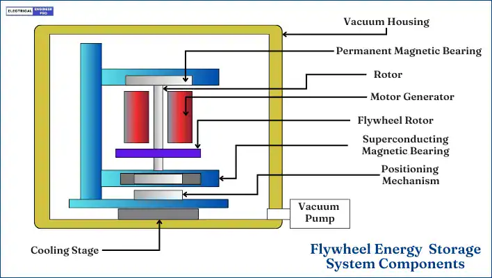
Basically, a modern flywheel energy storage system (FESS), consists of five key components,
- Flywheel rotor
- Electrical machine
- Bearings
- Power electronic interface
- Housing
Flywheel Rotor
The Flywheel rotor is the heart of the flywheel energy storage system, storing and releasing energy. It’s designed to hold as much energy as possible at a given speed while staying strong under the stresses of rotation and heat.
A rotor made from low-density, high-tensile-strength materials will have higher specific energy (energy per mass), but its energy density (energy per volume) remains unaffected by the material’s density.
Mostly, the rotor is attached to a shaft supported by bearings, and this shaft also serves as the rotating part of the motor or generator. The rotor-shaft assembly can be positioned either horizontally or vertically. Rotors are typically made from either composite materials or metal.
Composite Flywheel
Composite materials are impressive due to their low weight and high strength. For high-speed rotors, materials like graphite composites, carbon fiber, epoxy and fiberglass are ideal because they are both lightweight and strong, enabling much higher rotational speeds. These rotors usually have a vertical shaft and can spin at speeds over 10,000 RPM, with some even reaching beyond 100,000 RPM.
Steel Flywheel
From a cost perspective, flywheel energy storage systems made with high-strength steels are ideal for maximizing energy per dollar spent. High-strength steel flywheels offer high energy density (energy per volume) because of their high mass density.
Additionally, they outperform composite materials in terms of thermal conductivity and availability. As a result, high-strength steel flywheels are particularly well-suited for stationary, ground-based, and large-capacity applications.
Electrical Machine
The electrical machine, also known as the integrated Motor-Generator (MG), is connected to the flywheel to manage the energy conversion and charging process.
When the machine acts as a motor, it charges the flywheel by speeding it up and drawing power from an electrical source. To extract the stored energy, the same machine acts as a generator, slowing down the flywheel during discharge.
The design of this machine is crucial. It needs to be highly efficient, have high power density, and have low idle and rotor losses. High efficiency ensures the flywheel energy storage system (FESS) works effectively.
Low rotor losses are important because most FESS operate in a vacuum, where heat removal is challenging. Additionally, low idle losses are important for storing energy over longer periods.
Common electrical machines used in FESS include induction machines (IM), switched reluctance machines (SR), and permanent magnet synchronous machines (PMSM).
Bearings
Bearings are essential to keep the rotor steady with minimal friction while supporting the flywheel. Depending on factors like weight, lifespan, and efficiency, the bearing system can be either mechanical or magnetic.
Traditionally, mechanical ball bearings have been used, but they come with higher friction and require more maintenance due to lubricant wear.
To reduce friction losses, two types of bearings are used: magnetic bearings and hybrid bearings.
Magnetic Bearings
Magnetic bearings don’t touch the rotor or shaft, which means they have low energy losses, they last a long time and don’t need lubrication. These features make them ideal for high-speed flywheel systems.
In simple terms, a magnetic bearing uses permanent magnets to lift the flywheel and controlled electromagnets to keep the flywheel rotor steady. This stability needs a sophisticated control system with costly sensors.
There are three types of magnetic bearings in a Flywheel Energy Storage System (FESS): passive, active, and superconducting.
Passive magnetic bearings (PMB) use permanent magnets to support some or all of the flywheel’s weight. Active magnetic bearings (AMB) use adjustable magnetic fields to counteract external forces acting on the rotor, adjusting the field strength as needed.
Superconducting magnetic bearings (SMB) use superconducting materials to create a magnetic force that supports the rotor. These materials need to be kept very cold, so cryogenic cooling systems are necessary.They are the best choice for high-speed applications because they can stabilize the flywheel without electricity or a positioning system. The main downside is their high cost.
Hybrid Bearings
Typically, mechanical bearings like ball bearings aren’t used to support a flywheel. Instead, they work alongside magnetic bearings in a hybrid system.
In these systems, magnetic bearings maintain vertical levitation, while mechanical bearings help with the translational and rotational movement.
This approach minimizes losses, makes the control system less complex, and offers a stable, cost-effective solution.
Power Electronics
The main role of the power electronics is to connect the AC electrical grid with the variable-speed flywheel. The power electronics draw power from the AC grid to drive the flywheel motor, spinning it up and recharging the wheel. It further inverts, regulates and shapes the AC electrical output of the system and sends the generated power back to the AC grid line.
This interface typically includes a bi-directional inverter/converter and a variable speed drive. The power flowing to and from the flywheel is managed at a DC link. To connect the Flywheel Energy Storage System (FESS) to an AC grid, another bi-directional converter is necessary. This converter can be single-stage (AC-DC) or double-stage (AC-DC-AC).
The power electronic interface has a high power capability, high switching frequency, and high efficiency. Typically, the converter is based on insulated-gate bipolar transistors (IGBTs).
Housing
The housing is made up of thick steel or another high strength material. This housing accommodates the rotor and serves two main purposes:
- It reduces aerodynamic drag.
- Contains the rotor in case of a failure.
Operating a high-speed flywheel at atmospheric pressure would result in huge aerodynamic drag losses, thus reducing overall efficiency. To minimize these losses, flywheels are placed in a vacuum housing to eliminate air drag. However, operating in a vacuum requires additional equipment, such as a vacuum pump and a cooling system.
The housing also acts as a safety measure. If the wheel breaks while spinning, the containment vessel slows or stops the fragments, preventing injury and damage to nearby equipment.
Also Read: Wind Energy 101: Explore the Basics of a Sustainable Future
Flywheel Energy Density
Energy density tells us how much energy is stored in a given space or material. It’s like asking how much energy we can pack into a specific area or amount of material.
For a flywheel energy storage system, the energy it can store mainly depends on two things:
- the weight of the rotor and
- how fast it spins.
The formula to figure out the energy stored in a flywheel is:
Ek = ½ Iω2
- I is the moment of inertia, which depends on the flywheel’s mass and how that mass is spread out relative to the axis of rotation.
- ω is the angular velocity, or how fast the flywheel is spinning.
Flywheel systems designed for storing a lot of energy (rather than delivering it quickly) usually have larger rotors. These larger rotors can spin faster, storing more energy because of their size and weight.
For example, imagine a typical flywheel energy storage system used to stabilize the power grid or provide backup power for industries. It might have an energy storage capacity of about 100 kWh and can discharge energy at a rate of 1 MW.
If this system is discharging energy at its maximum rate of 1 MW, it would take about 6 minutes to use up all the stored energy. That’s because 100 kWh divided by 1000 kW equals 0.1 hours, or 6 minutes.
So, the amount of backup power a flywheel energy storage system can provide depends on how much energy it can store, how fast it can discharge that energy, and the power needs of whatever it’s supporting.
Also Read: Power of Solar and Solar Energy technologies Explained
Applications of Flywheel Energy Storage
Flywheel energy storage systems (FESS) have a range of applications due to their ability to store and release energy efficiently and quickly. Here are some of the primary applications:
- Grid Energy Storage Regulation: FESS helps maintain grid stability by absorbing and supplying power to match demand and supply fluctuations. It can store excess energy during low demand periods and release it during peak demand times, ensuring a balanced grid load.
- Renewable Energy Integration: FESS can smooth out the intermittent power supply from renewable sources like wind and solar, providing a more stable output. It allows for the storage of excess energy generated during peak production times for later use when production is lower.
- Uninterruptible Power Supply (UPS) Backup: FESS provides instant power backup in case of power outages, ensuring continuous operation of critical systems in hospitals, data centers, and industrial processes.
- Regenerative Braking: In electric and hybrid vehicles, FESS can store energy captured during braking and then use it to assist in acceleration, improving overall efficiency.
- Power Quality Improvement: FESS can mitigate power quality issues such as voltage sags, swells, and harmonic distortions in industrial power systems.
- Backup Power for Telecom Towers: FESS can provide reliable backup power to telecom towers, ensuring continuous communication services during power outages.
- Space Satellite Power Systems: In satellites, FESS can store energy from solar panels and provide power during periods when the satellite is in the Earth’s shadow.
- Military Applications: FESS can be used in remote military bases to store energy from renewable sources or generators, providing reliable power supply and reducing dependence on fuel logistics.
- Energy Management: FESS can enhance the reliability and efficiency of microgrids and off-grid power systems, particularly in remote areas or islands.
FAQs
How does flywheel energy storage compare to battery storage?
Flywheel energy storage systems offer higher power density and faster response times, making them ideal for short-duration, high-power uses like grid stabilization. Batteries have higher energy density, better for long-term storage. Flywheels also have longer lifespans and lower maintenance needs than batteries.
Can flywheel energy storage be used in residential applications?
Flywheel energy storage is mainly used in industrial and grid applications but can also support homes with renewable energy or uninterruptible power needs. However, cost and space requirements may limit its use in individual households.
How is the energy efficiency of a flywheel system measured?
The energy efficiency of a flywheel system is measured by the round-trip efficiency, which is the ratio of the energy output to the energy input. It accounts for losses due to friction, air resistance, and energy conversion inefficiencies. Modern flywheel systems can achieve round-trip efficiencies of 85-95%.
How long can a flywheel store energy?
The duration for which a flywheel can store energy depends on the system design and application. Typically, flywheels are used for short-term storage ranging from seconds to several minutes. Advanced systems with low friction and air resistance can store energy for longer periods, but they are generally not designed for long-term energy storage like batteries.
How do flywheels contribute to renewable energy integration?
Flywheels help integrate renewable energy by providing grid stability and frequency regulation. They can rapidly absorb and release energy to smooth out fluctuations from intermittent renewable sources like wind and solar. This ensures a more reliable and consistent power supply, facilitating higher penetration of renewables in the energy mix.
Can flywheel energy storage be used in electric vehicles?
Yes, flywheel energy storage can be used in electric vehicles (EVs), particularly for applications requiring rapid energy discharge and regenerative braking. Flywheels can improve vehicle efficiency by capturing and storing braking energy, which can then be used to accelerate the vehicle, reducing overall energy consumption.
How does the vacuum enclosure improve flywheel performance?
The vacuum enclosure significantly reduces air resistance (aerodynamic drag) around the spinning flywheel. By operating in a low-pressure environment, the flywheel can maintain higher rotational speeds for longer periods, reducing energy losses and improving overall efficiency.

