Problem Statement
A 37 KW , 3 phase, 415 V induction motor draws 56 A and 33 KW power at 410 V. What is the apparent and reactive power drawn by the motor at the operating load?
Before going into the solution of the numerical lets understand what apparent, active, reactive power is and their relationship with power factor.
Also Read: Energy Manager Exam | Co-generation power plant Numerical problem with solution
Power Triangle
The power triangle is a graphical representation that illustrates the relationship between real power (P), reactive power (Q), apparent power (S), and power factor (PF) in an AC (alternating current) circuit. These quantities are related by the following mathematical expression:
[latex]S^{2} = P^{2}+Q^{2}[/latex]
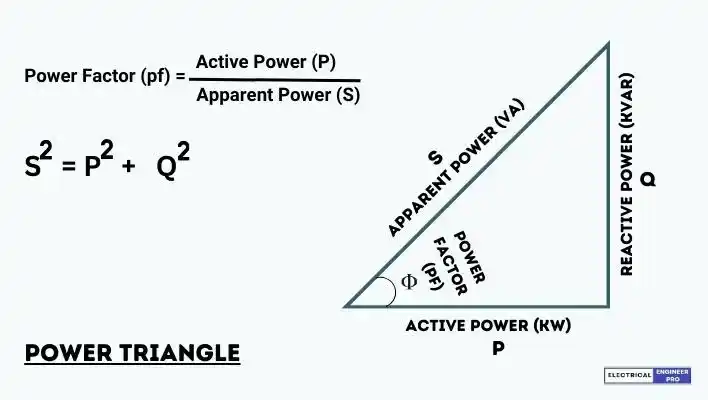
The power triangle is often represented graphically as a right-angled triangle, where the horizontal leg represents real power (P), the vertical leg represents reactive power (Q), and the hypotenuse represents apparent power (S). This triangle helps engineers and technicians visualize the relationships between these power components in AC circuits.
As shown in the figure, the quantities are
- Active power (P), or “true power” given in watts (W)
- Reactive power (Q), given in volt ampere reactive (var) 2
- Apparent power (S), given in volt ampere (VA)
- Power factor (p.f.), the ratio of active power to apparent power.
Active power
Active power (P) is also known as Real power or Actual power. It is consumed by the resistive elements in an electrical circuit. It is the component of power that performs useful work, such as driving motors, producing light or heating. Active power is measured in watts (W) and is a scalar quantity.
In the context of AC (alternating current) circuits, Active power is the time-averaged power that is dissipated as heat or converted into mechanical work. It is the portion of the power that is in phase with the voltage and current wave-forms.
Active power is a crucial parameter in understanding the efficiency and performance of electrical devices and systems, as it represents the actual useful output or work done by the electrical energy.
Reactive power
Reactive power does not perform any useful work but is necessary for maintaining voltage levels and supporting the operation of inductive or capacitive loads. It is measured in volt-amperes reactive (VAR).
Reactive power (Q) represents the power consumed and returned to the source in an AC (alternating current) circuit without being converted to any useful work.
Unlike Active power, which is the real power that performs work, Reactive power oscillates between the source and the load without doing any net work over a complete cycle.
Reactive power arises due to the presence of reactive elements like inductors and capacitors in a circuit. Inductive loads, such as motors and transformers, consume reactive power, while capacitive loads produce reactive power.
Utilities and industries often aim to manage reactive power to maintain stable voltage levels, reduce losses, and improve the overall efficiency of the power system. Capacitors and inductors can be strategically added or removed from a system to balance reactive power and improve power factor.
Apparent power
Apparent power (S) is a measure of the total power in an AC (alternating current) circuit, taking into account both the Active power and Reactive power. It is expressed in volt-amperes (VA) and is the vector sum of the Active power (measured in watts) and the Reactive power (measured in volt-amperes reactive or VARs).
Understanding and managing Apparent power is crucial in power systems, as it helps in sizing equipment, determining system capacity requirements, and assessing the efficiency of electrical systems. Proper management of Apparent power is essential for maintaining voltage levels, minimizing losses, and ensuring the reliable operation of electrical networks.
Also Read: Calculate motor temperature rise from unbalanced voltage | Energy Manager Exam question
Power Factor
The power factor (PF) is the cosine of the angle (θ) between the real power and the apparent power in the phasor diagram. Mathematically, it is expressed as:
Power Factor (PF)=cos(Φ)
The power factor can also be determined using the following relationship involving Active power, Reactive power and Apparent power:
[latex]pf = \frac{Active Power}{Apparent Power}[/latex]
In the power triangle:
- Φ is the angle between the real power and the apparent power.
- The cosine of Φ is equal to the ratio of real power to apparent power.
A high power factor (close to 1) indicates that a significant portion of the apparent power is being converted into real power, meaning the system is more efficient. Conversely, a low power factor (close to 0) indicates that a significant portion of the apparent power is reactive power, and the system is less efficient.
Improving the power factor is often a goal in power systems, as it helps to reduce losses, improve voltage regulation, and maximize the efficient use of electrical power. Capacitors or other power factor correction devices can be employed to adjust the power factor and bring it closer to unity in cases where it is lower than desired.
Useful formulas
- Active power P (in kW)
- Single phase (1 phase and neutral): P = V.I.cos Φ
- Three phase (3 wires + neutral): P = √3.U.I.cos Φ
- Reactive power Q (in kvar)
- Single phase (1 phase and neutral): Q = V.I.sin Φ
- Three phase (3 wires + neutral): Q = √3.U.I.sin Φ
- Apparent power S (in kVA)
- Single phase (1 phase and neutral): S = V.I
- Three phase (3 wires + neutral): S = √3.U.I
where:
V = Voltage between phase and neutral
U = Voltage between phases
I = Line current
Φ = Phase angle between vectors V and I.
Solution
Now let’s go to the solution of the problem. It’s quite simple and easy. Firstly, we have to check what’s given the numerical.
Also Read: How to find 3-phase AC motor parameters? Energy Manager exam question.
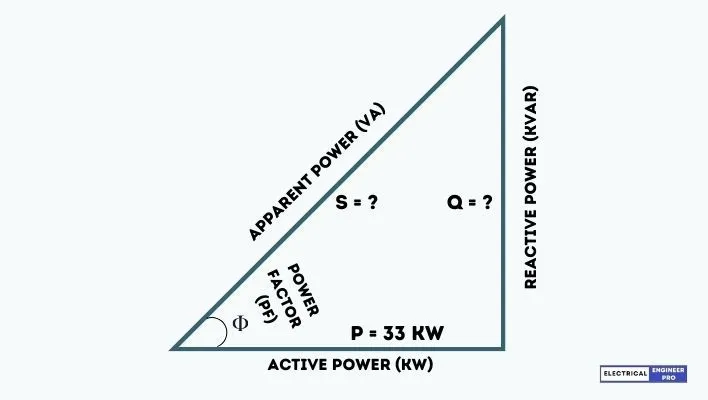
| It is given in the numerical that the induction motor draws 56 A and 33 KW power at 410 V. |
| That means power drawn by the motor is Active power = 33 KW and Apparent & Reactive power is not given. |
| So to find Apparent Power S = 1.732 x 410 x 56 = 39766.72 VA = 39.76 KVA |
| For Reactive Power (Q), we have to use power triangle formula which is, |
| [latex]S^{2} = P^{2}+Q^{2}[/latex] |
| [latex]39.76^{2} = 33^{2}+Q^{2}[/latex] |
| Q = 22.17kvar |
| Therefore, at 33 KW active power the induction motor is drawing an apparent power of 39.76 KVA and 22.17 Kvar of reactive power. |