Welcome to our comprehensive guide on Earthing! In this post, we delve into the critical role of earthing in safeguarding lives and equipment from earth faults. Establishing a robust earth connection, alongside equipotential bonding and effective protection mechanisms, is imperative. Electrical engineers and technicians must grasp the relevant codes and practices to ensure timely disconnection of electric supply for optimal safety. Join us as we unravel these essential concepts in earthing.
Also Read: Types of High Voltage Circuit Breakers | Explained
In this article, the terms "Earthing" and "Grounding" are used interchangeably. However, the IEEE Green Book presents a compelling case for favoring the term "Grounding." It contends that an electrical ground may not always be situated close to the earth (meaning soil). For instance, in a high-rise building, the electrical ground for someone working on the top floor is far above the earth. Despite IEEE's remarkable argument, we will use the term "Earthing" in this article to denote the common electrical reference point.
What is earthing?

Earthing in a power system is essentially the process of connecting the metal parts of electrical equipment or specific components like the neutral point in a star-connected system to the earth, typically through soil. This connection can be established using wires, copper/GI strips or other devices like resistors or circuit breakers, depending on the requirements.
Now, why do we go through the trouble of grounding? Well, while there are plenty of reasons which you’ll discover in the article, let’s focus on two main purposes for now.
Firstly, grounding helps protect the power system itself. For instance, if there’s a fault like a phase-to-earth fault on one of the lines in a star-connected system, and the neutral point is grounded through a relay via circuit breaker, a substantial fault current will flow through it.
This current will be detected by the relay and send a signal to the circuit breaker to trip, effectively isolating the faulty line and preventing any further damage to the rest of the system.
Secondly, grounding is essential for ensuring the safety of people. Let’s say there’s an issue with insulation, and the live conductor comes into contact with the metal frame of a piece of equipment. Without proper grounding, anyone touching that metal could be at risk of receiving a dangerous electric shock, which could even prove fatal.
Grounding provides a safe path for fault currents to flow into the earth, thereby reducing the risk of electric shock for anyone in contact with the equipment. So, it’s not just about protecting the system; it’s also about safeguarding human lives.
Also Read: Power Supply System | A Comprehensive Guide
What is the Purpose of Earthing?
- Earthing an electrical system is crucial for safety. It ensures,
- It provides uninterrupted and Improved service.
- Ensures safety of both equipment and human life
- It reduces the risk of critical electric shock for individuals near earthed facilities.
- In substations, earthing aims to,
- Create a uniform potential surface, aligning with zero or absolute earth potential.
- Ensures all non-live parts of equipment are at earth potential, keeping operators safe.
- Earthing provides a stable environment for sensitive electronic equipment by maintaining stable voltage levels to prevent over-current or voltage surges.
- It offers a low earth fault loop impedance, aiding automatic disconnection of the power supply when faults occur in exposed conductive parts.
- Earthing controls potential rise, also known as touch voltage, on non-current carrying metal parts during earth-fault situations, enhancing safety for individuals and animals nearby.
- It also provides a secure route to channel lightning current safely to the ground, averting potential damage.
Good To Know

Earth Fault Loop Impedance: Impedance/resistance encountered by fault current under earth fault condition is called Earth Fault Loop Impedance, which means the impedance of the earth fault current loop (phase to earth loop) starting and ending at the point of earth fault.

Touch Voltage: The potential difference between the ground potential rise (GPR) and the surface potential at the point where a person is standing while at the same time having a hand in contact with a grounded structure.
What is Equipment Earthing?

Equipment Earthing, also known as Equipment Grounding or Protective Earthing, is essentially about making sure that the non-current-carrying metal parts of electrical equipment are connected to the earth in a way that keeps them safe and stable. For example,
- Imagine the metal enclosure of your electrical switchgear panel. Equipment grounding is all about linking these non-current-carrying metal parts to the earth i.e. soil. This setup ensures that if there’s ever a problem with insulation, like a breakdown, the metal enclosures remains at the same potential as the earth, which is super important for safety.
Now, why is this so important? Let’s break it down by looking at its basic objectives:
- Keeping People Safe: One of the biggest reasons is making sure that anyone around the equipment isn’t at risk of getting zapped by dangerous electric shock. By grounding the equipment, we’re reducing that risk to a minimum.
- Preventing Fire Hazards: Another important job of equipment grounding is to stop things from catching fire. If there’s a problem and electricity starts flowing where it shouldn’t, grounding makes sure it doesn’t get out of control and start any fires. It’s like a safety net to prevent any fiery mishaps.
- Optimizing System Performance: And last but not least, proper equipment grounding contributes to the overall performance of the electrical system. By keeping everything grounded, we’re helping the system run smoothly and efficiently, without any troubles or snags.
So, equipment grounding isn’t just about playing it safe, it’s also about keeping things running smoothly and ensuring everyone stays out of harm’s way around electrical equipment.
Also Read: Importance of Power Transmission Lines | Explained
What is System Earthing?
System Earthing or System Grounding is the process of connecting certain electrical parts of the power system, like the neutral point of a star-connected system or a conductor of a transformer’s secondary, to earth.
This type of earthing is necessary because,
- Keeping Currents in Check: System earthing for low voltage setups is all about making sure that the electrical currents flowing through the system stay in line. By connecting certain parts to the earth, we’re basically keeping a lid on how much voltage these conductors can carry. This helps maintain the insulation levels that keep everything running smoothly and safely.
- Protecting the System: One of the main goals of system earthing is to make sure our protective devices, like circuit-breakers or fuses, can do their job quickly and effectively if there’s a fault. We want them to spring into action right away to isolate any issues and keep the system running smoothly.
- Avoiding Extra Loops: Now, when it comes to system earthing, we usually only earth one point, like the neutral in certain systems. Why? Because if we start earthing multiple points, we run the risk of creating local loops in the system. And trust me, we don’t want that because it could lead to all sorts of unwanted circulating currents messing with our gear and communication circuits.
Types of System Earthing
Worldwide, the earthing systems are categorized as TT System, TN System and IT System.
The letters used to denote earthing system are derived from the French language. The description of letters is as follows,
| The first letter refers to the relationship of the power system (source) to earth. | |
| T | ‘T’ means Terra which means Earth and refers to direct connection of one point to earth. |
| I | ‘I’ means Isole, which signifies that all the live parts are insulated from earth, or one point connected to earth through current limiting impedance. |
| Second letter refers to the relationship of the exposed-conductive-parts of the installation to earth. | |
| T | ‘T’ means Terra which means Earth and represents direct electrical connection of exposed conductive parts to earth, independently of the earthing of any point of the power system. |
| N | ‘N’ stands for Neutre, indicating Neutral. It signifies the direct electrical link of exposed conductive parts to the grounded point of the power system. In AC systems, this grounded point typically corresponds to the neutral point or, in cases where a neutral point is unavailable, to a line conductor. |
| The third and fourth represent the purpose of neutral and protective conductors. | |
| S | ‘S’ means separate neutral and protective earth functions provided by separate conductors i.e. PE and N conductor. |
| C | ‘C’ illustrates combined neutral and protective earth functions provided by same conductor i.e. PEN/CNE conductor |
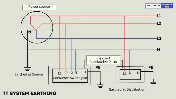
- In the TT system, both the supply source and the metal frames of the installation are directly connected to earth.
- In a TN system, the supply source has one or more points, like the neutral point of a transformer or generator, directly earthed at the source end. The metal frames of the installation serve as a return path for earth fault currents, connected to the earthed points of the source through protective conductors. TN systems further branch into TN-S, TN-C, and TN-C-S systems.
- In a TN-S system, the supply source links directly to earth, while metal frames connect to the earthed neutral through the metal sheath of the supply cable.

- In a TN-C system, neutral and protective functions combine into a single conductor throughout the system.

- A TN-C-S system mirrors TN-S but with the supply cable sheath doubling as the neutral, forming a Protective Earthed Neutral (PEN) conductor. Earth and neutral are separate conductors in this setup, known as Protective Multiple Earthing (PME).

- In IT system may have the source unearthed or earthed through high impedance, with exposed conductive parts of the installation linked to electrically independent earth electrodes.

What is Equipotential Bonding?
Equipotential bonding is the practice within a system whereby all exposed conductive components, such as metal frames of active equipment and equipment bodies, as well as extraneous conductive elements like metallic items embedded in building concrete and metallic pipelines, are interconnected with the main earthing terminal. This ensures that they are all maintained at the same potential in the event of an earth fault, thus promoting safety and preventing electrical hazards.

| Extraneous Conductive Part = Building Structural Steel |
| Extraneous Conductive Part = Building Metallic Pipe Network |
| Earth Electrode = TT and IT System |
| PE = TN System |
| Protective Conductors = Main Protective Bonding Conductor, Supplementary Protective Bonding Conductor, Circuit Protective Conductor, Earthing Conductor. |
Protective Equipotential Bonding
When equipotential bonding is specifically geared towards safety, we call it “Protective Equipotential Bonding.” The main aim here is to automatically disconnect the power supply if needed, ensuring safety in case of any mishap.
In each building, we ensure that the earthing conductor, the main earthing terminal, and a few other conductive parts are linked up in this protective equipotential bonding setup:
- Any metallic pipes bringing services into the building, like gas, water, firefighting systems, sewage, and so on.
- If they’re accessible during normal use, we also connect structural conductive parts like metallic central heating and air-conditioning systems.
- And if it’s feasible, we include the metallic reinforcements of the constructional reinforced concrete.
Supplementary Equipotential Bonding
Supplementary Equipotential Bonding, also known as Local Equipotential Bonding, serves a crucial role in enhancing safety against electric shock. It’s essentially an extra layer of protection added on top of fault protection measures. By implementing supplementary equipotential bonding, we not only bolster safety but also further minimize voltage occurrences during an earth fault.
During the design phase of an electrical system, if the fault loop impedance required for automatic disconnection of the power supply cannot be achieved solely through standard equipotential bonding, it becomes crucial to integrate supplementary equipotential bonding.
Also Read: What is interconnected power system or grid?
What is Neutral Earthing?
Neutral grounding involves linking the neutral point of a 3-phase system to the earth, either directly or through various circuit elements like resistance or reactance. This practice is termed as neutral grounding.
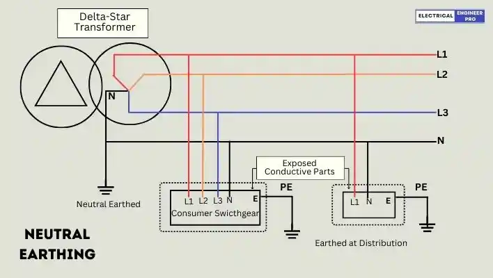
Neutral grounding ensures the safety of both personnel and equipment. During an earth fault, current flows through the earthed neutral, prompting protective devices such as fuses to isolate the faulty conductor from the rest of the system.
Methods of Neutral Grounding
- Solid Earthing
- Resistance Earthing
- Reactance Earthing
- Peterson-coil Earthing
Advantages of Neutral Grounding
- Helps maintain nearly constant voltages across healthy phases, preventing them from exceeding line to ground voltages.
- Eliminates high voltages resulting from arcing grounds.
- Enables protective relays to offer protection against earth faults. If a fault occurs, the protective relay triggers to isolate the faulty line.
- Safely discharges over-voltages caused by lightning to the earth.
- Enhances safety for both personnel and equipment.
- Improves service reliability.
- Reduces operating and maintenance expenses.
What are extraneous conductive parts and exposed conductive parts?
Earthing can be defined as connecting all the extraneous conductive parts and the exposed conductive parts of an electrical installation to the soil, i.e. Earth. These connections are done through GI or copper conductors. The connections provide a path for fault currents and hold the parts of electrical installation as close as possible to earth potential which is zero volts.
Extraneous conductive parts
The extraneous conductive parts that need to be connected to either the main earthing terminal or the earth electrode of the installation include the following
- Gas pipes,
- Other service pipes and ducting,
- Risers and pipes of fire protection equipment,
- Exposed metallic parts of the building structure
- Lightning conductors.
Exposed Conductive Parts
Exposed conductive parts that must be connected using protective conductors to the main earthing terminal of the installation include:
- All metal components related to the wiring system (excluding current-carrying parts), such as cable sheaths, armor, conduit, ducting, trunking, boxes, and catenary wires.
- Exposed metal components of transformers.
- Neutral points of transformers.
- Exposed metal components of generators.
- Neutral points of generators.
- Metal frames of low tension and high tension electric panels, motors, etc.
Main Components of Earthing
- Earthing or Protective Conductors: Earth or protective conductors are employed vertically and horizontally over walls, ceiling and floors to connect the extraneous and exposed conductive parts through MET or directly to the electrodes of the main earth grid.
The conductors used are mostly bare round copper/GI or GI/copper flat strips. Depending upon the installation some also utilize single core multi stranded aluminium or copper cables for earthing.
- Electrodes
A. Plate Electrodes: According to the guidelines provided in IS 3043, the plate electrodes typically have dimensions of at least 600 mm × 600 mm. These plates are commonly made of cast iron (CI) with a thickness of not less than 12 mm, preferably ribbed, and should have the earth connection joined at a minimum of two separate points.
Alternatively, plate electrodes can be constructed from galvanised iron (GI) or steel, with a thickness not less than 6.3 mm, or from copper with a thickness of not less than 3.15 mm. Plate electrodes are buried in such a way that the top edge is at a depth of no less than 1.5 m below the ground surface.

B. Pipe or Rod Electrodes: Cast iron pipes, with a diameter of not less than 100 mm, length ranging from 2.5 to 3 m, and thickness of 13 mm, are commonly used as electrodes.
Another method involves directly driving a 40 mm diameter GI pipe or a 40 mm diameter mild steel rod into soil, placing them at a depth of 1.25 m below ground level. The thickness of the pipe used for earthing should not be less than 1.6 mm for GI/copper/stainless steel pipes.
Earth rods predominantly consist of round copper, steel-cored copper, or galvanised steel, with diameters ranging from 13 to 19 mm and lengths from 1220 mm to 2440 mm.
3. Main Earthing Terminals (MET): For electrical installations with voltages ranging from 250 V to 650 V, it’s essential to have a main earthing terminal (MET) positioned between the main earth grid and the protective conductor of the power source.
The MET serves as a central hub for distributing earthing conductors throughout the installation. Depending on the size of the electrical setup, there may be one or multiple METs.

The primary function of the MET is to establish a reference point for the installation. It typically consists of a terminal or bar where protective conductors and functional earthing conductors are connected. METs are commonly constructed using galvanised iron (GI) for copper strips and are installed using wooden or PVC insulators on walls and ceilings.
4. Inspection Chambers (Earth Pits): An inspection chamber of approx. 300 mm X 300 mm or 450 mm X 450 mm is built around the earth electrode. These chambers are also known as Earth Pits.
After driving the rods/pipes into the ground there is constant need for inspection, testing & irrigating the rods to achieve low earthing resistance. Hence the chambers are built and covered with CI or heavy duty PVC material covers.
5. Earth enhancing compound: Earth enhancing compounds are employed to decrease the resistivity of the soil around the earth electrode. Commonly used substances for this purpose include sodium chloride (NaCl), commonly known as common salt, calcium chloride (CaCl2), sodium carbonate (Na2CO3), copper sulfate (CuSO4), salt, soft coke, and a mixture of salt and charcoal in appropriate proportions. Certain earthing manufacturing companies offer their proprietary compounds designed for use with earth electrodes.
Also Read: Smart Grid | The Ultimate Guide
FAQs
What is the basic objective of Earthing?
The basic objective of system earthing is to ensure efficient and fast operation of protective device in the case of earth faults The system earth fault loop impedance should be such that, when any earth fault occurs, the protective device (circuit breakers or fuses, etc will operate to isolate the faulty main or equipment.
What is the difference between electric earthing and grounding?
Earthing and grounding mean the same thing. They’re used interchangeably, as mentioned in paragraph 8 of the ‘Foreword’ of IS 3043-2018. The difference in names comes from how British and American English use language differently. The British call it ‘earthing’, while Americans say ‘grounding’. International standards like IEC and IS use ‘earthing’, while IEEE and ANSI standards use ‘grounding’.
What is the Earth fault in Electrical system?
An earth fault occurs when an unintended connection between a phase conductor and the earth is established, typically due to insulation failure or equipment malfunction.
How does equipment earthing differ from other types of earthing methods?
Equipment earthing specifically focuses on grounding the metal components of electrical devices and machinery, whereas other types of earthing methods may involve grounding structures, electrical systems, or specific points within a system.
What factors are considered for designing an effective earthing system?
Factors to consider include soil resistivity, fault current levels, equipment grounding requirements, environmental conditions, proximity to lightning-prone areas, and compliance with local regulations and standards.
How does soil resistivity affect the effectiveness of an earthing system?
Soil resistivity determines the resistance of the earth electrode to the flow of fault currents. Lower resistivity soils offer better conductivity and lower resistance, resulting in more effective earthing systems, while higher resistivity soils may require additional measures to achieve satisfactory earthing performance.
How does lightning protection relate to earthing systems in buildings and structures?
Earthing systems play a crucial role in lightning protection by providing a low impedance path for lightning discharge currents to dissipate safely into the ground, thereby minimizing the risk of structural damage, fire hazards, and electrical surges within the facility.

